background image

71

Issued: 28.02.2005

Strider MD 4 Plus

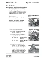
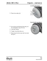
Adjusting the clamping bolts:

(1.) Loosen the locking screws (2)

(Philips head No. 2.)

The clamping tightness is adjusted by
turning the clamping bolts.
The clamping tightness should be set so
that the clamping lever can be closed by
hand without requiring too much force.

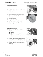
Adjusting the clamping tightness:

Unlock the clamping lever (1).

Unlocking the clamping
lever

Adjusting the clamping

bolts

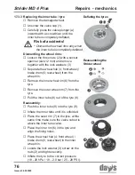
(2.) Turn the clamping bolts in the

appropriate direction:

(a) turn to right = increase clamping

tightness

(b) turn to left = decrease clamping

tightness

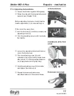
(3.) Align the clamping lever (1).

In order that the clamping bolt
fits precisely into the receptacle
when coupling the drive unit (see
chapter 14.4.1), the clamping
lever (1) must be leaning slightly
to the left when it is unlocked
(oriented to around 7 o’clock)

Tools required:
1 x screwdriver; Phillips head No. 2

Repairs - mechanics

17.3.1 Adjusting the drive lock clamping bolts

17.3 Mechanics

Содержание MD 4 Plus

Страница 1: ...NURSING BEDS PFLEGEBETTEN S T R I D E R OPERATING MANUAL MD 4 Plus Order number E1 04 058 001...

Страница 2: ......

Страница 3: ...h construction and material selection A large variety of useful accessories rounds off our range in addition to the Strider This Operating Manual assumes that the suitability of the user for Strider u...

Страница 4: ...nce between seat and tiller 24 5 2 2 Adjusting the armrest width 24 5 2 3 Adjusting the armrest height 25 5 2 4 Adjusting the backrest inclination 26 5 3 Adjusting the headrest height 26 5 4 Adjusting...

Страница 5: ...r 44 11 2 Charging the batteries 45 11 3 After charging 46 12 0 Things to know 47 12 1 The battery charger functioning principle 47 12 2 The batteries 47 12 2 1 What are batteries for cyclic use 47 12...

Страница 6: ...g 60 15 0 Maintenance and Inspection 61 15 1 Daily maintenance before start of journey 61 15 2 Weekly inspections tyre pressure 61 15 3 Annual inspection inspection timetable 62 16 0 Troubleshooting 6...

Страница 7: ...ries 83 17 6 2 Refitting battery cables 84 18 0 Temporary storage 85 19 0 Appendix 85 19 1 Nameplate 85 19 2 Specifications 86 19 2 1 General data 86 19 2 2 Dimensions 87 19 3 Torque for fixing screws...

Страница 8: ...e Days Healthcare scooter is constructed for use both indoors and outdoors Class B European standard EN 12 184 It is intended to increase the mobility of persons who are both physically and mentally c...

Страница 9: ...or alcohol Only use the scooter for its correct intended use Only use the scooter when it is in perfect working order If any breakdowns occur stop using the scooter immediately and secure it against u...

Страница 10: ...drive down steps Do not drive backwards down gradients stairs or kerbstones or over obstacles Risk of accidents Check correct functioning of the brakes and lighting unit indicators headlights before e...

Страница 11: ...s during preparation for transport and maintenance work Always carry out any work to be done with great care Always try to get help from a second person especially when stowing parts for transport Onl...

Страница 12: ...s of water and visit a doctor Always change any clothing soiled with battery acid immediately 1 7 Safety information about electronics Accident hazard due to failures Radio television radio transmissi...

Страница 13: ...ng the Strider on 3 Battery Charger 4 Operating Manual 2 0 Extent of delivery After receiving your Strider please check the following that the delivery is complete in accordance with the list below th...

Страница 14: ...er Battery charge display Drive lever reverse Drive lever forwards Horn button Hazard indicator switch Headlight switch Indicator switch Shopping basket Tiller Indicators and headlight Indicators and...

Страница 15: ...d of non use and to refresh existing knowledge of operation It is imperative that you follow the instructions given in the main manual 1 Turn the seat to the out side NOTE Before starting driving adju...

Страница 16: ...16 Issued 28 02 2005 Strider MD 4 Plus ON 5 Check the battery charging state 4 Switch on the Strider 3 Fasten the seat belt Brief instructions...

Страница 17: ...tructions The drive lever position controls the speed variably right up to maximum driving speed Reverse Forwards Max driving speed Max driving speed 8 Driving Operate the drive lever slowly until the...

Страница 18: ...18 Issued 28 02 2005 Strider MD 4 Plus 9 Braking release drive lever 1 10 Direction indicators 1 Horn 2 Hazard lamps 3 Lights 4 Brief instructions...

Страница 19: ...MD 4 Plus 4 2 Transporting the Strider 1 Remove the seat 2 Remove the rear panelling 3 Remove the lighting cable Dismantling the Strider stages 1 to 10 5 Remove the battery plug 4 Separate the front...

Страница 20: ...005 Strider MD 4 Plus 8 Unlock the drive unit 9 Tilt the drive unit away 10 Remove the chassis 6 Remove the battery belts and batteries 7 Fold the tiller down Brief instructions Reassembling the Strid...

Страница 21: ...ackrest forward 2 NOTE The seat must be removed from the Strider in order to adjust the seat height You should try to get help from a second person if possible or contact your dealer Removing the seat...

Страница 22: ...he seat height h is adjusted by using the holes in the seat support Pull the seat support out as far as the required height until the correct hole appears in the seat tube hole Push the lower clamping...

Страница 23: ...after inserting the seat it is not possible to turn the seat or to pull the seatlock the seat is not properly locked Place the rear panelling onto the drive unit from above While doing this Introduce...

Страница 24: ...kwards Tilt the backrest backwards Pull the locking lever 1 and move the backrest backwards to the required position 2 Let go of the locking lever and engage the locking mechanism by pushing the backr...

Страница 25: ...Pull the armrests upwards to the required height until the hole in the armrest support appears through the hole in the seat tube 5 Reinsert the Allen screw and tighten Adjusting the armrest height To...

Страница 26: ...ion 7 Let go of the locking lever and engage the locking mechanism by pushing the backrest slightly forwards and backwards Accident hazard if backrest is not properly engaged Ensure that the backrest...

Страница 27: ...sh the tiller forwards or backwards into the required position Release the locking lever Ensure that the tiller is engaged correctly by moving it backwards and forwards Accident hazard due to non enga...

Страница 28: ...ines ramps take a trial run with the Strider in an area with no pedestrians or in a closed off area always steer the Strider using both hands on the handlebars always keep your feet in the foot area w...

Страница 29: ...sed danger of tipping when climbing or descending gradients if the Strider is loaded at the back and additionally the backrest captain s seat is leant towards the back and the seat has been adjusted t...

Страница 30: ...es don t try to drive over obstacles which are too high example kerbstones remedy always climb up kerbstones at lowered entry areas such as driveways DO NOT try to climb an obstacle when on an incline...

Страница 31: ...se start practicing kerb climbing with small kerbs Adjust the speed controller to maximum speed Press the drive lever fully forward and try to clear the kerb in one go The speed of the scooter should...

Страница 32: ...inued even if the overload protection device allows you to do so The motor could become dammaged by such sustained excessive temperatures If the motor is overloaded the following happens the Strider b...

Страница 33: ...ery charge display If the scooter is at standstill it is often the case that the battery charging state is shown higher than it actually is The display can vary greatly while the vehicle is travelling...

Страница 34: ...void steep inclines as much as possible do not carry any unnecessary luggage drive at an even speed do not accelerate or brake unnecessarily The driving range will be decreased if you drive with headl...

Страница 35: ...Opening the seat belt Pull the turning lock 1 on the seat forwards Turn the seat 90 towards you 2 and engage Getting on or off Please observe the following before getting on or off Press the red unloc...

Страница 36: ...hen get on 7 2 Seat belt adjusting for length and putting on Turn the seatbelt closer 1 at right angles to the seat belt Adjust the length by pulling the appropriate belt side a shortening the belt le...

Страница 37: ...s increased Before turning the seat always ensure that the scooter is on an even and solid surface The switch 1 is located to the right of the tiller Operation indicator Switching the Strider on The s...

Страница 38: ...ble maximum driving speed for the required drive level NOTE Use the adjustment facilities to adjust the speed to suit local conditions Select a lower speed if you are driving through narrow gaps on in...

Страница 39: ...ged 7 7 Driving driving forwards driving in reverse Is the light working Switch on to test in working order Are the indicators working Switch on to test in working order Are the batteries charged Chec...

Страница 40: ...the brake lever slowly in order to brake the Strider To use the handbrake pull the brake lever 2 slowly towards the handlebar 7 9 Indicating 7 8 2 Using the handbrake Handbrake Driving the Strider Em...

Страница 41: ...Strider off Press the horn button 5 It will sound for as long as you hold the button down Using the horn 7 11 Using the horn 7 12 Switching off parking the Strider OFF NOTE If you drive with the head...

Страница 42: ...h the hazard lamps on uses up the battery The driving range will be reduced Pressure switch 6 switch on press switch once switch off press switch again The switch indicator lamps shows whether the haz...

Страница 43: ...itch on automatically and brake the Strider Push the shopping basket 1 from above into the basket holder receptacles 2 on the tiller 10 0 Attaching the shopping basket NOTE Use the shopping basket onl...

Страница 44: ...h off device which prevents overcharging the batteries Do not leave the battery charger connected to the scooter for more than 24 hours The batteries can be charged overnight Switch the Strider off be...

Страница 45: ...er is located on the left of the tiller 1 Connect the battery charger plug 4 to the Strider charging socket Connecting the battery charger Charging the batteries Switch the Strider off Switchingoff En...

Страница 46: ...e Strider jack socket Removing the mains plug Removing the battery charger Charging the batteries LED information at battery charger during charging LED Colour Meaning a Red battery charger switched o...

Страница 47: ...e full only the current required for battery charging flows which means that battery overcharging is prevented 12 1 The battery charger functioning principle 12 2 The batteries 12 2 1 What are batteri...

Страница 48: ...ive unit is located in the rear of the Strider and consists of the following main components the drive 1 the control unit 2 and the batteries 3 Drive unit the drive NOTE The control unit and its cabli...

Страница 49: ...or 4 and the rear light and direction indicator 5 Lighting 12 9 Wheels and tyres The Strider is fitted with inner tubes and tyres of size 4 0 5 12 8 Anti tipping wheels The anti tipping wheels reduce...

Страница 50: ...et go the drive lever which is then returned to its central position by a spring The Strider is then braked by the drive motor When the Strider is at a standstill or has been switched off it is braked...

Страница 51: ...Strider can be dismantled in a few steps so that it can also be easily transported in smaller vehicles When transporting take particular care to ensure that the batteries are securely fastened and ma...

Страница 52: ...Seat unit 13 3 1 Working step summary 13 3 2 Removing the seat Clamping and crushing hazard Increased hazards due to clamping or crushing result due to the high component weight such as batteries duri...

Страница 53: ...lling Remove the rear panelling Press the locking device A on the plug and disconnect the electric cable connecting plug 5 to the rear lights and rear indicators 13 3 3 Removing the rear panelling Rem...

Страница 54: ...ontal Folding the tiller down Separating the front connector 13 3 5 Folding the tiller down 13 3 6 Disengaging the drive unit from the chassis Remove the battery belts 8 Remove the batteries Removing...

Страница 55: ...the drive unit Separating the chassis NOTE Use rear bumper as grip to stowe the drive unit Open the clamping bolt clamping lever 15 and fold the clamping bolt upwards Unlockingthedriveunit Tilt drive...

Страница 56: ...ames 1 over the drive unit holding bolts 2 Fold the drive unit forwards 3 Folding the drive unit in Transporting the Strider 13 4 AfterTransport Reassembly 13 4 1 Engaging the drive unit to the chassi...

Страница 57: ...down Lockingthedriveunit Reconnect the front unit connecting plug 6 Connecting the motor plug NOTE The clamping tightness should be set so that the clamping lever can be closed by hand without requir...

Страница 58: ...elightcable Plug in the battery cable connecting plugs 11 Plug in thebatteryplugs Route the safety straps 9 10 across the batteries as illustrated in the photograph and tighten Place the batteries in...

Страница 59: ...5 Fitting the seat NOTE If after inserting the seat it is not possible to turn the seat or to pull the seatlock the seat is not properly locked Place the rear panelling onto the drive unit from above...

Страница 60: ...rfaces Please observe instructions for use on the detergents to avoid damage to the component surfaces Never direct water jets onto the fittings on the tiller or drive unit components Light soiling or...

Страница 61: ...tions Screw the valve cap back on Maintenance and Inspection Check the brakes by driving slowly and then braking Check that the lights and indicators are functioning correctly Make a visual check of w...

Страница 62: ...nt functions easily Armrests width adjustment no damage functions easily Backrest upholstery no damage fixed securely Backrest adjustment no play in joint functions easily Seat upholstery no damage fi...

Страница 63: ...joint functions easily Wheels no damage fixed securely Tyres no damage tyre pressure Antitipper wheels no damage rollers turn easily Component Tiller Panelling no damage fixed securely Grip rubbers no...

Страница 64: ...and inspection Component Displays and controls electric system electronic system Dashboard switches no damage safe function Dashboard displays no damage safe function Indicator lamps no damage safe f...

Страница 65: ...ngaged lever remains engaged Maintenance and inspection Assessment OK Defective Description Component inspection for Component Displays and controls electric system electronic system Drive lever No da...

Страница 66: ...in you will find information about troubleshooting and fault remedy in the following lists 16 2 Troubleshooting Fault Cause Remedy Switch the scooter on chapter 7 4 Battery not pluged in Front unit co...

Страница 67: ...nit Short circuit in electrical equipment Visit your dealer Check battery charge display battery discharged Strider switched to push mode Drive lever pressed while switching on Fault on drive lever Au...

Страница 68: ...attery charger Battery charger defective Batteries completely discharged Replace fuses chapter 17 5 1 Replace fuses chapter 17 5 2 Plug in batteries chapter 13 4 3 Plug in front unit connector chapter...

Страница 69: ...switch off overload protection active Check battery charge display Batteries discharged Scooter switched to push mode Connecting plugs at the control unit interrupted Fault in control unit fault in ma...

Страница 70: ...amping and crushing while carrying out any repair work This applies particularly to all rotating and adjustable parts of the scooter such as around the steering wheels The Strider must be lifted in or...

Страница 71: ...the clamping lever Adjusting the clamping bolts 2 Turn the clamping bolts in the appropriate direction a turn to right increase clamping tightness b turn to left decrease clamping tightness 3 Align th...

Страница 72: ...slightly to the right around 1 o clock when locked Tighten the locking screw 6 Checking alignment Tightening the locking screw Repairs mechanics Checking the clamping bolt setting Checking the setting...

Страница 73: ...re bolted to the front wheel rims Repairs mechanics Front wheel Rear wheel Loosen the self locking nut 2 for the wheel fastening size 19 mm Secure the Strider against rolling away Lift the Strider and...

Страница 74: ...er the Strider Retighten the self locking nut Place the key 5 in the slot in the drive shaft 6 Fitting the rear wheel NOTE The key is rectangular Place it with its widest side in the axle slot Push th...

Страница 75: ...e the washer 8 Locating the washer Securing the rear wheel Repairs mechanics Press the protective cap onto the wheel fixing nut Screw the wheel fixing self locking nut 9 and tighten it size 19 mm Lowe...

Страница 76: ...tyre Pull the inner tube 8 out of the tyre 9 Deflating the tyres Reassemblingthe Strider wheel Risk of accidents Dismantle the wheel rims only when the inner tube is completely deflated Reassembly Pus...

Страница 77: ...apter 18 0 Before adjusting the brake check that the handle adjustment 1 is screwed fully in Loosen the adjustment element locknut 4 on the front wheel Turn the adjusting screw 5 until resistence can...

Страница 78: ...peated until the brake functions correctly uniform brake effectiveness on both front wheels when braking from movement see chapter 7 8 2 Braking wheel free running when brake not applied Repairs mecha...

Страница 79: ...TE The working sequence for front and rear indicators is the same and is described using photographs of the rear lights Insert the rear or front light lens and secure with the fixing screws 17 4 1 Rep...

Страница 80: ...l the bulb out of the lamp holder Fitting a new bulb 1 Align the bulb base pins with the grooves in the lampholder and push the bulb into the lampholder 2 Press the bulb in lightly and lock by turning...

Страница 81: ...er head 2 10 A fuse Light 3 10 A fuse charging socket The Strider is fitted with the following fusible fuses A wiring diagram with fuse sizes is located on the control unit cover Wiring diagram To rep...

Страница 82: ...e insulating cap of fuse holder Repairs fuses 2 types of battery fuses are used Type 1 70 A fuse strip fuse Fuse holder in the plus pole cable of the batteries To replace Fuse Unscrew fuse housing Pul...

Страница 83: ...ays transport and store batteries in an acid proof container Caution acid Observe safety information in chapter 1 6 BATTERIES ARE HAZARDOUSWASTE Used and defective batteries must be properly disposed...

Страница 84: ...chapter 13 3 4 First 1 loosen the terminal on the battery negative terminal black cable with a ring spanner size 10 mm and remove the cable Then 2 loosen the terminal on the battery positive terminal...

Страница 85: ...Strider for longer periods e g over the winter you should prepare it as follows Remove soiling and dust Charge the batteries completely Check the tyre pressure and adjust if necessary Place the Strid...

Страница 86: ...re size 3 00 5 Tyre pressure 28 PSI 2 0 bar Working voltage battery voltage 24 Volt Batteries 2 batteries of make please see chapter 17 6 Storage temperature 40 C bis 65 C Ambient temperature 25 C bis...

Страница 87: ...87 Issued 28 02 2005 Strider MD 4 Plus 19 2 2 Dimensions Appendix dimensions...

Страница 88: ...of the scooter The scooter consists of metal and plastic components electronic components electrical cables and batteries Disposal of the individual materials must be carried out in accordance with en...

Страница 89: ...been subject to undue wear and items subjected to misuse Unauthorized changes or modifications will forfeit your warranty If a defect or fault is discovered the Days Healthcare supplier dealer from w...

Страница 90: ...ied out Date _______ Dealer s stamp __________________________ Signature Date _______ Dealer s stamp __________________________ Signature Date _______ Dealer s stamp __________________________ Signatu...

Страница 91: ......

Страница 92: ...DAYS MEDICAL AIDS LTD Bridgend Ind Est BRIDGEND CF31 3TP TEL 01656 657495 FAX 01656 767178 Dealer s stamp...

Отзывы: