


ANTENNA SITE SELECTION (120° AND 180° ANTENNA)
____________________________________________________________________________________________
____________________________________________________________________________________________
42S042D
SERIES 8060 6-METER EARTH STATION ANTENNA
2-13
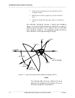
VERIFYING CLEAR
LINE-OF-SIGHT
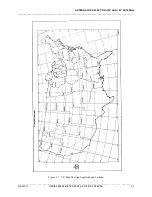
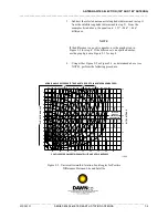
Once the operational clearance has been verified, it is necessary to verify a clear
line-of-sight. This ensures that the antenna may be aimed at desired satellite(s)
without obstruction between the satellite(s) and any portion of the reflector.
When using the satellite(s) aiming coordinates for a particular site, be sure that
there are no trees, buildings, power lines, etc., between the dish location and the
satellite. It is important that this clearance includes the total dish surface area
and that nothing is blocking any portion of the dish surface.
VERIFYING
ABSENCE OF
SIGNAL
INTERFERENCE
For optimal signal reception, it is important that the antenna site selected be free
of strong microwave or other signal interface. Microwave systems in the vicinity
of a selected antenna site can cause interference. If a known source of
interference (e.g., a Bell System microwave tower) is close by, it may be
necessary to have a site survey performed to determine if the site selected is
suitable. Two of the companies which perform these services are:
Comsearch, Inc.
Spectrum Planning, Inc.
11720 Sunrise Valley Drive
P.O. Box 831360
Reston, VA 22091
Richardson, TX 75083 - 1360
(703) 620-6300
(214) 680-1000
VERIFYING
AVAILABILITY OF
POWER
REQUIREMENTS
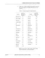
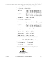
The power requirements will vary depending on the options purchased with the
6M antenna. Table 2-2 provides a list of the power requirements for each
option. Table 2-3 provides a list of the circuit breaker requirements for each
option. Verify that adequate power is available prior to finalizing the selection
of the site.
Table 2-2. Power Requirements
______________________________________________________
Antenna Motorization - Domestic (60 Hz)
Azimuth Axis
208V ac, 3-phase, 1.9 amp max (single speed -120°)
208V ac, 3-phase, 3.6 amp max (single speed -180°)
208V ac, 3-phase, 14.8 amp max (variable speed -180°)
Elevation Axis
208V ac, 3-phase, 1.9 amp max (single speed -120°)
208V ac, 3-phase, 3.2 amp max (single speed -180°)
208V ac, 3-phase, 14.8 amp max (variable speed -180°)
Polarization Axis
208V ac, 3-phase, 0.24 amp
Содержание 8060 Series
Страница 65: ......
Страница 66: ......
Страница 67: ......
Страница 68: ......
Страница 69: ......
Страница 70: ......
Страница 71: ......
Страница 72: ......
Страница 73: ......
Страница 74: ......
Страница 75: ......
Страница 76: ......
Страница 77: ......
Страница 78: ......
Страница 79: ......
Страница 80: ......
Страница 81: ......
Страница 82: ......
Страница 83: ......
Страница 84: ......
Страница 85: ......
Страница 86: ......
Страница 87: ......
Страница 88: ......
Страница 89: ......
Страница 90: ......
Страница 91: ......
Страница 92: ......
Страница 93: ......
Страница 95: ......
Страница 97: ......
Страница 98: ......
Страница 100: ......
Страница 102: ......
Страница 103: ......
Страница 104: ......
Страница 105: ......
Страница 106: ......
Страница 107: ......
Страница 108: ......
Страница 109: ......
Страница 110: ......
Страница 111: ......
Страница 112: ......
Страница 113: ......
Страница 114: ......
Страница 115: ......
Страница 116: ......
Страница 117: ......
Страница 118: ......
Страница 119: ......
Страница 120: ......
Страница 121: ......
Страница 122: ......
Страница 123: ......
Страница 124: ......
Страница 125: ......
Страница 126: ......
Страница 127: ......
Страница 128: ......
Страница 129: ......
Страница 130: ......
Страница 131: ......
Страница 132: ......
Страница 133: ......
Страница 134: ......
Страница 135: ......
Страница 136: ......
Страница 137: ......
Страница 138: ......
Страница 139: ......
Страница 140: ......
Страница 141: ......
Страница 142: ......
Страница 143: ......
Страница 144: ......
Страница 145: ......
Страница 146: ......
Страница 147: ......
Страница 148: ......
Страница 149: ......
Страница 150: ......
Страница 151: ......
Страница 152: ......
Страница 153: ......
Страница 154: ......
Страница 155: ......


