i
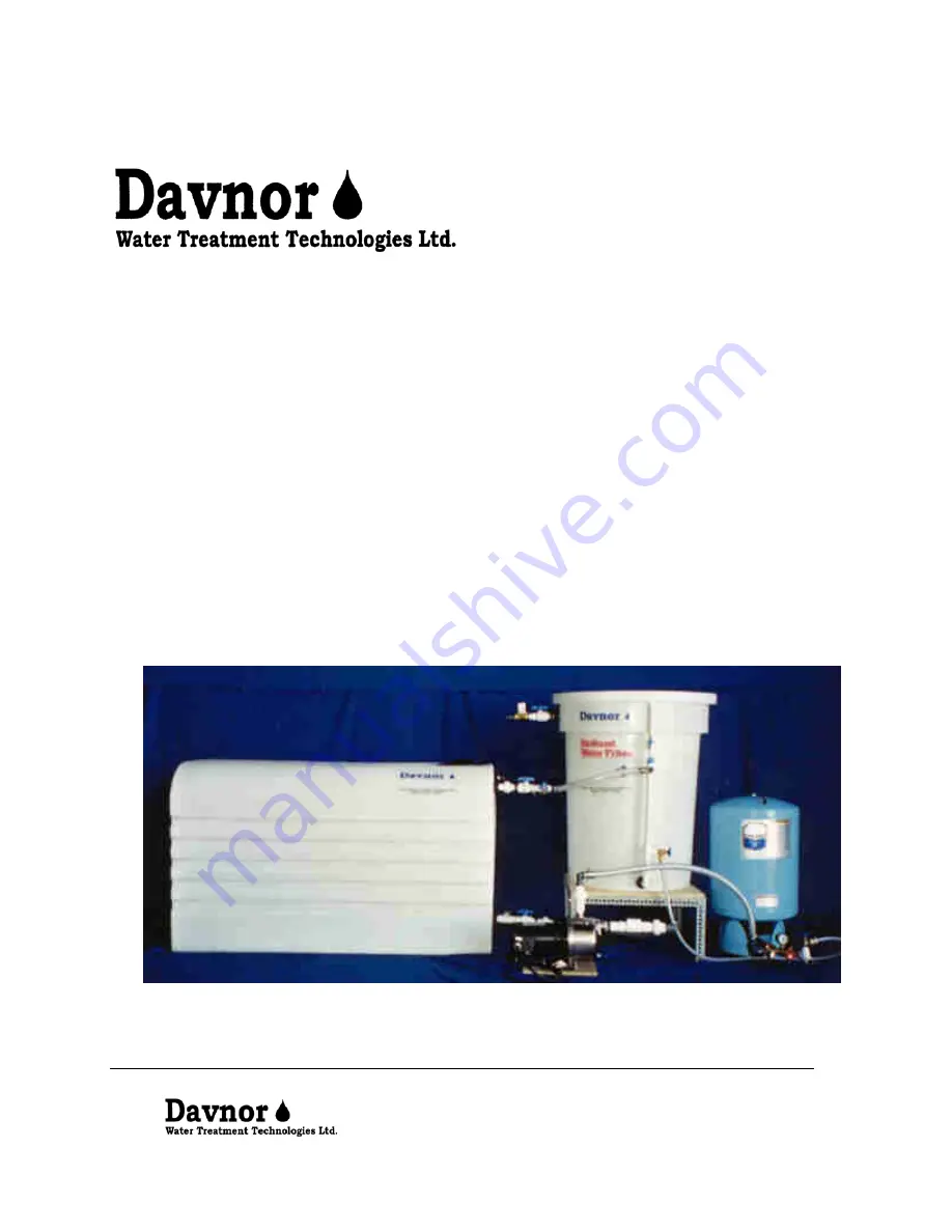
Automated Surface Water Treatment
System
INSTALLATION, OPERATIONS &
MAINTENANCE MANUAL
Страница 1: ...i Automated Surface Water Treatment System INSTALLATION OPERATIONS MAINTENANCE MANUAL ...
Страница 2: ...sembly 2 4 Filter Media Installation 6 5 System Commissioning 7 6 Sanitizing Procedure 8 7 System Start Up 9 8 Operation 9 9 Filter Maintenance 10 10 Degassing the Filter Media 11 11 Winterization 11 12 Refilling 12 13 Decommissioning Moving 12 14 Trouble Shooting 13 ...
Страница 3: ...upplies Do not attempt to treat wastewater heavily polluted or contaminated water Please contact a Davnor representative if there is any uncertainty regarding the treatability of the water 2 Operations Summary The Davnor Water Treatment Technologies Ltd surface water system is a slow sand filtration process The operation of the system is automated for the removal of giardia cysts cryptosporidia oo...
Страница 4: ...nlet floor drain or drainage pipe and electrical outlet Place the filter on the stand place the storage tank pump and pressure tank Note A qualified plumber should make the connection from the untreated water inlet to the filter system and the filtered water outlet to the distribution line Your pump and your solenoid valve may need to have electrical plugs attached to them This work should be perf...
Страница 5: ...Maintenance Drain Valve 14 Filter Outlet Valve 15 Anti siphon Valve 16 Filter Overflow 17 Solenoid Valve to high level float switch 18 Storage Tank Inlet Valve with Union Connection 19 Sampling Valve 20 Storage Tank Float Valve 21 High Level Float Switch to the solenoid valve 22 Low Level Float Switch to the pump 23 Storage Tank Outlet with Union Connection Shutoff Valve and Drain Valve 24 Check V...
Страница 6: ... storage tank assemblies Inlet assembly Outlet assembly Overflow assembly Step 3 Place the pump and pressure tank Step 4 Install the low level and high level float switches in the storage tank shown in Figure 3 1 To do this start by removing the supporting ring on the manway of the filtered water storage tank Position the low level switch near the bottom of the filtered water storage tank and the ...
Страница 7: ... filter and the filtered water storage tank Leave an air space between the overflow drain line and the drain to prevent the drain from backing up into your filter Step 8 Install the filter CIP reverse flow assembly downstream of the pump figure 3 3 Step 9 Connect the hose from the CIP reverse flow valve downstream of the pump to the lower valve on the filter standpipe Step 10 Connect the filtered ...
Страница 8: ... it through the diffuser to prevent mixing of previously installed sand layers Approximately 15 cm of water above the sand is desirable Step 3 Add the underdrain gravel to the level indicated figure 4 1 Step 4 Level the surface of the underdrain gravel Referring to Figure 4 1 add the 3 sand to the level indicated on the filter body Repeat this procedure with the 2 sand and the 1 sand Note There ma...
Страница 9: ...ved to the down position Step 4 Open the filter inlet valve to begin filling Adjust the mechanical float valve in the filter such that the water level does not go higher than the filter overflow Now wait until the water level reaches the maximum water level in the filter Figure 4 1 Note See Table 2 to obtain the filter flow rate It is critical that the filter be operated at this flow Faster flows ...
Страница 10: ...a could get into the water filter piping For this reason sanitizing is recommended after installation On some water supplies additional periodic sanitizing is also recommended Step 1 Prepare a dilute bleach solution for sanitizing by mixing 5 ml of common household bleach Javex Clorox etc with 1 litre of water Step 2 Close the filter inlet valve and allow the filter water level to drop to the paus...
Страница 11: ... Step 5 Water should continue to run through the system until the water level in the filtered water storage tank is just below the overflow The high level float switch should close the solenoid valve and allow the filter to drain to the paused water level The mechanical float valve will stop the flow of water if the high level float switch is out of adjustment Adjust the mechanical float valve and...
Страница 12: ...assembly Figure 9 2 Step 5 Turn the handle on the clean in place CIP mechanism to agitate the top of the sand while the water level is slowly filling from the bottom Allow the water level to rise until the diffuser basin is filled with water Step 6 Once the diffuser basin is full of water stop stirring the CIP and wait for 30 seconds Now flush the dirty water from the sand surface through the main...
Страница 13: ...e Close the anti siphoning valve Step 4 The water will slowly enter the filter from the bottom expelling any trapped gasses through the filter surface Continue to bottom fill the filter until you don t see any more air bubbles surfacing Be sure to run this for a minimum of 15 minutes to ensure all gas pockets are filled with water Periodically tap the sides of the filter during this process Drain ...
Страница 14: ...age tank inlet valve Sampling valve Refill hose Flow rate adjustment valve Filter outlet valve Figure 12 1 13 Decommissioning Moving The system can be decommissioned and moved to a new location Care must be taken to label all parts and components for ease of re installation Note Do not move the filter with media in it Step 1 Perform a complete maintenance cycle on the filter Step 2 Close and disco...
Страница 15: ...ection 5 Note that the valve will have to be reset again when the water temperature increases Water not entering the filter 1 Filter inlet valve not fully open Check the valve to the filter 2 Mechanical float valve out of adjustment Re adjust as required 3 Solenoid valve closed See solenoid valve not functioning below Storage tank overfilling 1 Mechanical float valve out of adjustment Re adjust as...