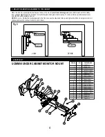
David Engineering & Mfg PDR UCMM50 Скачать руководство пользователя страница 3

Fig 5

Fig 3

A

View under cabinet

Cabinet front lip

View “A”

Enlarged view

Fig 4

Position flush to front 
edge

Wood screws

Bayonet plate

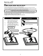
Lay the monitor on a soft surface, face down, and attach the mount using 75mm or 100mm VESA hole 
pattern and  the 4 screws supplied. See 

fig 5

Using the 4 wood screws supplied, attach the mounting bracket to the underside of the cabinet. Place the 
narrow end of the plate up against the cabinet front  lip. A spacer and longer screws  may be required if the lip is 
deeper than 2”. See 

fig 3

 and 

fig 4

2   ATTACH THE MOUNT TO THE MONITOR


3


 1  FASTENING THE MOUNTING PLATE TO THE  CABINET BOTTOM


NOTE: Do not over tighten the bracket mounting screws as damage to the monitors  internal mounting threads could occur.

75mm & 100mm
VESA hole pattern

M o u n t i n g  s c r e w s

Содержание PDR UCMM50

Страница 1: ...n equipment Mounts by A division of David Engineering Mfg Inc Suitable for displays with 75mm 100mm VESA mounting pattern Simple to adjust no tools required 2 Adjustable height from 6 8 to 8 8 100 deg tilt and 360 deg rotation Quick monitor removal with exclusive Bayonet locking system Features Thank you for purchasing the PDR monitor mount with the exclusive Bayonet locking system Toensurecustome...

Страница 2: ...N A P P R O P R I AT E L O C AT I O N B Y C H E C K I N G T H E S T R U C T U R E A N D D U R A B I L I T Y F O R S A F E T Y A N D A C C I D E N T P R E V E N T I O N Do not alter any of the parts Do not use broken parts This 2 CAUTION WARNING WARNING The cabinet where the mount is to be installed must be capable of long term support of the total load of the monitor and mount Measures should be t...

Страница 3: ...od screws supplied attach the mounting bracket to the underside of the cabinet Place the narrow end of the plate up against the cabinet front lip A spacer and longer screws may be required if the lip is deeper than 2 See fig 3 and fig 4 2 ATTACH THE MOUNT TO THE MONITOR 3 1 FASTENING THE MOUNTING PLATE TO THE CABINET BOTTOM NOTE Do not over tighten the bracket mounting screws as damage to the moni...

Страница 4: ...the front Loosen the side knob fold up and tighten the tilt knob Larger monitors or shallow cabinet will not allow monitors to fully retract 6 12 16 5 4 3 14 13 7 1 15 8 2 10 9 18 17 11 19 ITEM NO QTY PART NUMBER 1 1 UCMM50 002 2 1 MDWM50 003 1 3 1 UCMM50 005 4 1 PMCW50 012 REV A 5 1 PMCW50 010 REV A 6 1 UCMM50 001 7 2 PDM 0013 REV A 8 1 UCMM50 006 9 4 PDM 0021 REV A 10 11 PDM 0008 REV A 11 4 PDM ...

Отзывы: