12: Front Panel Assembly
PRC1099A-MS
12-7
12.2
Connectors
12.2.1
Audio Connectors
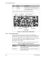
The PRC1099A front panel provides two Audio connectors that connect
handsets, headsets, and CW key devices to the radio. The PRC1099A supports
the following audio devices.
This section provides the Audio connector pin assignments with a description
of each pin assignment.
Table 12-2 Supported Audio Devices
Device
Description
DSP9000-HS
High-level encrypting handset. Normal operation is fully
automatic—user selects plain or cypher mode. Refer to the
Datron Product Catalog for more information.
MHS
H-189/U repairable military handset.
H-250/U
Disposable, Noise-canceling version of the MHS.
H140/U
Ruggedized headphones.
H3M
Headset-boom microphone. Single earphone profile with
clip-on PTT switch.
KYR
Morse key with 36 in. (0.9m) cable.
LS-R
Loudspeaker with 5-pin MIL-STD connector.
SHS
Scrambling handset with 5-pin MIL-STD connector. The
SHS-KIT programming kit is sold separately.
Pin
Name
Description
A
GND
Shield ground for the audio device cable.
B
RX AUDIO
Receive audio output to handset or headset
speaker to Audio/Filter board J6 connector.
C
PTT
PTT from the handset or headset.
D
TX AUDIO
Transmit audio input from handset or headset
microphone to Audio/Filter board J6
connector.
A Shield Ground
B Rx Audio
C PTT
Tx Audio D
CW Key E
+12V SW F
Содержание PRC1099A
Страница 4: ......
Страница 8: ......
Страница 35: ......
Страница 49: ...3 Audio Filter Board 3 14 PRC1099A MS Figure 3 2 Audio Filter Board Component Locations 738221 Rev J ...
Страница 65: ......
Страница 71: ...4 1650 kHz IF Board 4 6 PRC1099A MS Figure 4 2 1650 kHz IF Board Component Locations 738028 Rev D ...
Страница 76: ......
Страница 86: ...5 Mixer Board 5 10 PRC1099A MS Figure 5 4 Mixer Board Component Locations 738217 Rev H ...
Страница 97: ......
Страница 103: ...6 Power Amplifier Board 6 6 PRC1099A MS Figure 6 2 Power Amplifier Board Component Locations 738617 Rev C ...
Страница 117: ...7 Antenna Tuner Board PRC1099A MS 7 9 Figure 7 2 Antenna Tuner Driver Board Component Locations 738346 Rev B ...
Страница 118: ...7 Antenna Tuner Board 7 10 PRC1099A MS Figure 7 3 Antenna Tuner Board Component Locations 738027 Rev D ...
Страница 125: ......
Страница 131: ...8 Synthesizer Board 8 6 PRC1099A MS Figure 8 2 Synthesizer Board Component Locations 738025 Rev A ...
Страница 163: ...9 Processor Board 9 14 PRC1099A MS Figure 9 2 Processor Board Component Locations 738218 Rev B ...
Страница 178: ...10 Display Board 10 8 PRC1099A MS Figure 10 1 Display Board Component Location Diagram 738220 Rev G ...
Страница 181: ......
Страница 185: ...11 Junction Board 11 4 PRC1099A MS Figure 11 1 Junction Board Component Locations 738222 Rev F ...
Страница 200: ......
Страница 207: ...13 Internal Options PRC1099A MS 13 7 Figure 13 3 ALE Board Component Locations 1 of 2 738215 Rev B ...
Страница 208: ...13 Internal Options 13 8 PRC1099A MS Figure 13 4 ALE Board Component Locations 2 of 2 738215 Rev B ...
Страница 241: ......
Страница 247: ...Index 6 T Technical specifications 1 2 Transmit path 2 4 U USB 1 4 see also Modulation modes USB LSB mode V VSWR 1 4 ...


