9: Processor Board
9-6
PRC1099A-MS
The display has its own interface bus lines, PA6 and PA7, which are display
data and display clock, respectively. Display bus operation is similar to the
control bus, except that there is no select line because the display is the only
device on the bus.
9.1.18
Memory Dump Feature
The PRC1099A is equipped with a memory dump feature that allows the
operator to quickly erase all frequencies and channel information stored in
memory (channels 00 through 99). The ability to quickly erase memory is
very useful to avoid compromising unit frequencies in the event of an enemy
capture.
To erase the frequencies stored in memory, hold the
DIGIT
knob down while
holding the
TUNE
knob up and then turn the radio on. The radio resets all
programmed frequencies to 2.000 MHz.
9.1.19
BITE Description
BITE is a series of built-in tests that enable the radio operator to test various
sections of the PRC1099A radio. The BITE software is capable of performing
tests on the following sections of the radio:
• Battery
• Antenna
• LCD display
• Processor RAM
• Receiver
• Transmitter
• Antenna tuner
The following sections describe the operation of the BITE program. They
provide an overview of the BITE program, describe each test step in detail,
include pass or fail indications, and areas of required operator interaction.
Operation
Before starting BITE, configure the radio as follows:
1. Install the whip antenna (or adapter, when using a long wire antenna).
2. Connect a handset to one of the audio connectors.
3. Set the Mode knob to
USB
.
4. Turn the
Vol
knob to
5
.
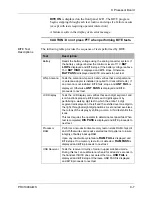
5. Initiate the BITE tests are by selecting
BITE TST
from the
OPT
menu.
6. Start the BITE test sequence by pressing the
Whip Tune
button.
Содержание PRC1099A
Страница 4: ......
Страница 8: ......
Страница 35: ......
Страница 49: ...3 Audio Filter Board 3 14 PRC1099A MS Figure 3 2 Audio Filter Board Component Locations 738221 Rev J ...
Страница 65: ......
Страница 71: ...4 1650 kHz IF Board 4 6 PRC1099A MS Figure 4 2 1650 kHz IF Board Component Locations 738028 Rev D ...
Страница 76: ......
Страница 86: ...5 Mixer Board 5 10 PRC1099A MS Figure 5 4 Mixer Board Component Locations 738217 Rev H ...
Страница 97: ......
Страница 103: ...6 Power Amplifier Board 6 6 PRC1099A MS Figure 6 2 Power Amplifier Board Component Locations 738617 Rev C ...
Страница 117: ...7 Antenna Tuner Board PRC1099A MS 7 9 Figure 7 2 Antenna Tuner Driver Board Component Locations 738346 Rev B ...
Страница 118: ...7 Antenna Tuner Board 7 10 PRC1099A MS Figure 7 3 Antenna Tuner Board Component Locations 738027 Rev D ...
Страница 125: ......
Страница 131: ...8 Synthesizer Board 8 6 PRC1099A MS Figure 8 2 Synthesizer Board Component Locations 738025 Rev A ...
Страница 163: ...9 Processor Board 9 14 PRC1099A MS Figure 9 2 Processor Board Component Locations 738218 Rev B ...
Страница 178: ...10 Display Board 10 8 PRC1099A MS Figure 10 1 Display Board Component Location Diagram 738220 Rev G ...
Страница 181: ......
Страница 185: ...11 Junction Board 11 4 PRC1099A MS Figure 11 1 Junction Board Component Locations 738222 Rev F ...
Страница 200: ......
Страница 207: ...13 Internal Options PRC1099A MS 13 7 Figure 13 3 ALE Board Component Locations 1 of 2 738215 Rev B ...
Страница 208: ...13 Internal Options 13 8 PRC1099A MS Figure 13 4 ALE Board Component Locations 2 of 2 738215 Rev B ...
Страница 241: ......
Страница 247: ...Index 6 T Technical specifications 1 2 Transmit path 2 4 U USB 1 4 see also Modulation modes USB LSB mode V VSWR 1 4 ...

