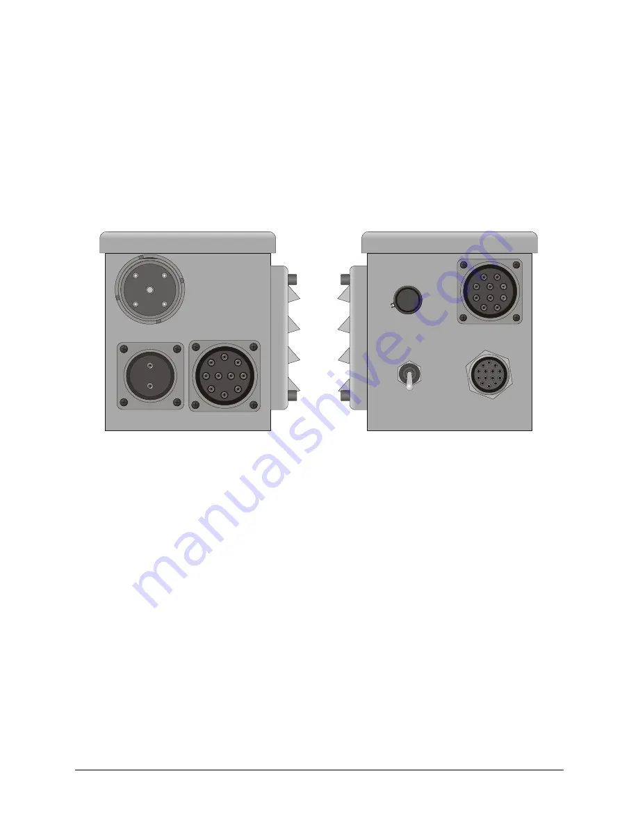
MT1099A-MS
3-1
CHAPTER 3
OPERATION
To operate the MT-1099A:
1. Do one of the following:
•
For 20W operation, install the MT-1099A according to section 2.3.1,
24 Vdc 20W Mobile System on page 2-3.
•
For 100W operation, install the MT-1099A according to section
2.3.3, 24 Vdc 100W Mobile System on page 2-4.
•
For 400W operation, install the MT-1099A according to section
2.3.5, 24 Vdc 400W Mobile System on page 2-5.
2. Turn the front panel switch to the POWER ON position to apply power to
the MT-1099A or to the SPEAKER ON position to also enable the built-in
external speaker. The POWER ON and SPEAKER ON positions also
provide power to the antenna tuner.
Note:
The power present at the DC OUT connector to the external RF
amplifier (RA100, RA400) is not switched. When source power is con-
nected to the DC IN connector, it also present at the DC OUT connector
even when the front panel switch is in the OFF position.
Figure 3-1. MT-1099A Front and Rear Panels
J5
DC IN
J4 DC OUT
J3
TUNER CONTROL
VOLUME
VOLUME
ON
POWER
ON
OFF
TRANSCEIVER
J1
J2 AMP CNTRL


