Installation and Use Manual
Datong Autosun
Power Control Co.,LTD
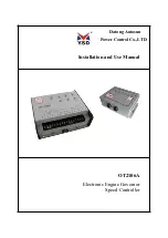
OT2106A
Electronic Engine Governor
Speed Controller
Страница 1: ...Installation and Use Manual Datong Autosun Power Control Co LTD OT2106A Electronic Engine Governor Speed Controller ...
Страница 2: ...ements 5 3 2 3 Requirements for the installation location 5 3 3 INSTALLATION DRAWINGS AND ELECTRICAL CONNECTION DIAGRAM 6 3 3 1 Connecting Wires 7 3 3 2 Electrical connection 8 3 4 INSTALLATION AND WIRING CHECK 8 3 4 1 Actuator installation check 8 3 4 2 Check electrical connections 8 3 4 3 Speed sensor installation check 8 四 COMMISSIONING 8 4 1 PRE SET 8 4 2 START ADJUSTMENT 9 4 3 SPEED DROOP ADJ...
Страница 3: ...egal operation directly turn off the power supply to carry out stop during the engine operating the engine is likely to arise uncontrolled serious accident may cause property damage or casualties Solution to this problem is linkage should contain a return spring the spring force size should be able to ensure that once the actuator power down pulling the fuel delivery immediately to the minimum pos...
Страница 4: ...OT2106A Electronic Engine Governor Speed Controller 3 Copyright 2010 Autosun Company ...
Страница 5: ...on will be automatically replaced by speed control function Adjustment range 25 to 100 of the controller output signal turn clockwise will increases the start up oil quantity Stable potentiometer Gain potentiometer Compensation potentiometer these three potentiometers are used to adjust and correct the control characteristics of the amplifier circuit so that the controller can adapt different type...
Страница 6: ... position signal Output to the driver is for negative is for positive Terminal 11 12 speed trim speed trim potentiometer is more than 100 Ω In differential mode it can be used to complete a manual synchronization or add and subtract load Terminal 13 14 15 differential rate more than 2 k Ω circle rate potentiometer They are used to adjust rate Terminal 6 spare manufacturer reserves no electrical co...
Страница 7: ...tection 1 5 Speed and Speed Frequency The engine speed is described by gear teeth tooth frequency which is detected by the engine speed sensor Through speed sensor Speed controller perceives the engine speed characteristics The control target is frequency Hz signal output by speed sensor rather than the speed r min of engine crankshaft The engine speed r min is proportional to the voltage signal f...
Страница 8: ... 5 35 s Output position signal 0 200 mA load impedance 30 45 Ω Actuator Compensation time constant adjustment range is 0 500 ms Differential rate 0 8 2000Ω potentiometer Application temperature range 40 85 Storage temperature range 55 105 Relative Humidity 38 95 when Vibration and shock 4 Gs vibration frequency range 5 500 Hz Shock 60 Gs Weight about 1 2 kg 三 Installation 3 1 Dismounting Before un...
Страница 9: ... 3 1 correct power connect WARNING If you use the battery to power the controller a charging device shall be equipped to maintain a stable voltage supply and make sure that the controller is not connected solely with the charging device Before removing the battery cables you should turn off the charging device first avoiding controller damage from the charging device 3 2 3 Requirements for the ins...
Страница 10: ...nor Speed Controller 6 3 3 Installation drawings and electrical connection diagram Controller installation outline is shown in figure 3 2 Electrical connection is shown in figure 3 3 figure 3 2 Controller installation Outline Drawing ...
Страница 11: ... should also be increased in order to meet the requirements All signal lines should be shielded to prevent electromagnetic interference signals picked up from nearby equipment All shielded should use twisted pair wire The shielded cable is connected to ground terminal of the housing below the terminal 9 with length no more than 5cm Make sure there is a conductor connecting controller terminal and ...
Страница 12: ...s is to prevent danger occurs when the engine can not stop 3 4 2 Check electrical connections According to Figure 3 3 check whether the electrical connector is correct and check the shield wire is connected to the ground terminal below the 9th terminal 3 4 3 Speed sensor installation check Check whether the speed sensor is damaged check whether the gap between sensor probe and the engine gear top ...
Страница 13: ...rting the engine make sure the installation connection and the pre set are correct Note Make sure the controller speed set range is within the actual needs of the engine work Emergency stop devices should be prepared to prevent overspeed or personal property damage when starting the engine 1 Stability adjustment If the engine is in a steady state skip this step and directly adjust the rated speed ...
Страница 14: ...ity potentiometer to lower stabilizing value NOTE Generally you do not have to turn the gain potentiometer to maximum to get the best dynamic characteristics Sometimes the gain should be slightly reduced in order to ensure the stability under various conditions change 4 Compensation adjustment If the engine continues periodic slight unstable running you should slowly increase actuator compensation...
Страница 15: ...rn clockwise start up fuel quantity potentiometer until the engine starts up In order to optimize engine starting characteristic the start up fuel quantity potentiometer can be appropriately adjusted When the speed controller is in the speed control state the start up fuel quantity control will lose its function Note For the engine which does not need start up fuel quantity control the potentiomet...
Страница 16: ...peed trim potentiometer in the middle position when commissioning 4 Close the power switch to power up the speed controller and actuator 5 Drag the engine and start 6 Run the engine into idle state cut off the overspeed protection switch wait for the cooling water lubricating oil reach the required temperature 7 Close the rated speed switch the engine accelerates to the rated speed 8 If running st...
Страница 17: ...supply flow rate to minimum position forcing the engine to stop To protect the controller from being shorted or overloaded a automatic circuit breaker is set in the output circuit After the short circuit or overload is repaired circuit breaker automatically recover During the open circuit protection the overheating circuit will be cooled so that the output position signal is 0 forcing the engine t...
Страница 18: ...ble 6 1 Table 6 1 Typical malfunction and solution Phenomena Probable cause Processing method The engine cannot started up the actuator does not move to the start fuel supply position Governor power is connected inversely or too low Check whether governor power is connected inversely or too low Actuators does not respond on the input signal from the controller If there is a voltage output between ...
Страница 19: ...is attached to a metal or other matter 4 If the speed is lower than the set value during the startup you should turn the rated speed potentiometer clockwise to increase the setting If clockwise adjustment does not produce the correct output signal you need to reset the rated speed potentiometer to the maximum position counter clockwise Idling potentiometer set value is too low Adjust the idle spee...
Страница 20: ...ation whether adjustment of the fuel supply connection is appropriate Check whether the fuel supply mechanism is moving fast with actuator input voltage When the overspeed protection device is operating normally check whether the shutdown action take place while engine is not over speeding Speed controller setup issues When the speed setting is counterclockwise set to maximum and the controller po...
Страница 21: ...be broken Idle speed potentiometer broken If instability occurs during the potentiometer adjustment you should replace the idle potentiometer When turn off rated speed switch the engine speed does not decrease Rated speed switch or wiring damage Check the voltage of terminal 5 and 2 if the value is less than 2V you should replace the switch or the wire Idle setting in the clockwise maximum Be care...
Страница 22: ...not supply as the actuator requirements Check whether the actuator which was connected to engine fuel supply control unit is idling clamping stagnation or overload The engine cannot run properly Manual control of the engine detect whether the instability reason is from the engine or the speed controller or actuator Input voltage is too low Check the power supply voltage If abnormality occurs durin...
Страница 23: ...OT2106A Electronic Engine Governor Speed Controller 19 ...
Страница 24: ...DA TONG Autosun Power Control CO LTD Address 7 Daqing East Road Datong City Shanxi Province PRC Contact telephone 86 0352 5099489 Fax 86 0352 5099521 Email sxdtysd yahoo com cn Site www ysd2000 com ...