10 Specifications and Theory of Operation
M1132382
10-7
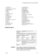
Electrical power
WARNING
The connection of equipment to the auxiliary mains
electrical outlets may increase the patient leakage
currents to values exceeding the allowable limits in the
event of a defective earth conductor.
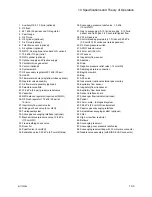
1. Anesthesia system
23. Breathing system
2. Power cord
24. Bag/Ventilator switch
3. AC inlet with breaker and line filter
25. ABS on switch
4. Isolation transformer
26. Canister switch
5. Inrush board
27. CO2 bypass switch
6. Fuses
28. Bulkhead connector
7. Line filter
29. Expiratory flow sensor
8. Outlet box
30. Inspiratory flow sensor
9. Universal power supply
31. O2 sensor
10. Battery, 12 V
32. Enhanced sensor interface board
11. DAQ board
33. ACGO select
12. On/Standby switch
34. O2 flush switch
13. O2 supply switch
35. AC power in/communication to system
14. Task light switch
36. LCD backlight 1
15. Task light
37. LCD backlight 2
16. Total flow sensor board (optional)
38. Left membrane switch
17. CPU board
39. Bottom membrane switch
18. LCD
40. Right membrane switch
19. ComWheel
41. USB I/O port
20. Ventilator engine board
42. Network I/O port (Ethernet)
21. Gas inlet valve
43. Patient monitoring port (Ohmeda Com)
22. Flow control valve
44. Serial I/O port
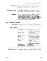
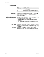
Supply voltage
100-120 or 220-240 Vac ±10% at 50 or 60 Hz
Average power
consumption
less than 50 VA
Note: Measured through the power cord when operated at the ventilation setting
VCV, TV = 1500 l/min, RR = 26, I:E = 1:2, and PEEP is Off; three gas TFS
option installed, LCD backlights at level 5, task light on maximum, and following
15 minutes of system running on battery power.
Inlet circuit
breakers
100-120 Vac
15 A
220-240 Vac
8 A
Outlet circuit
breakers
110-120 Vac
Japan
220-240 Vac
(3) 2 A
(1) 3 A
(2) 2A
(1) 4A
(3) 1 A
(1) 2 A
System leakage
current limit - do
not exceed:
UL and CSA rated systems (U.S.A. and Canada): less than
300
μ
amps for the system and all systems connected to
electrical outlets.
IEC rated systems (Not U.S.A. and Canada): less than 500
μ
amps for the system and all systems connected to
electrical outlets.
Resistance to
ground
less than 0.2
Ω
Содержание Aespire View
Страница 1: ...Aespire View User s Reference Manual Software Revision 6 X...
Страница 16: ...Aespire View 1 8 M1132382...
Страница 46: ...Aespire View 3 16 M1132382...
Страница 50: ...Aespire View 4 4 M1132382...
Страница 88: ...Aespire View 7 8 M1132382...
Страница 112: ...Aespire View 9 10 M1132382...
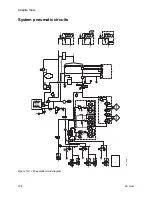
Страница 114: ...Aespire View 10 2 M1132382 System pneumatic circuits Figure 10 1 Pneumatic circuit diagram AC 20 001...
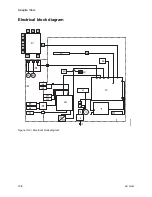
Страница 118: ...Aespire View 10 6 M1132382 Electrical block diagram Figure 10 2 Electrical block diagram AC 20 008...
Страница 137: ...10 Specifications and Theory of Operation M1132382 10 25 Figure 10 9 Gas composition related errors AB 74 027...
Страница 148: ...Aespire View I 4 M1132382...

