6
Vector Scope Area
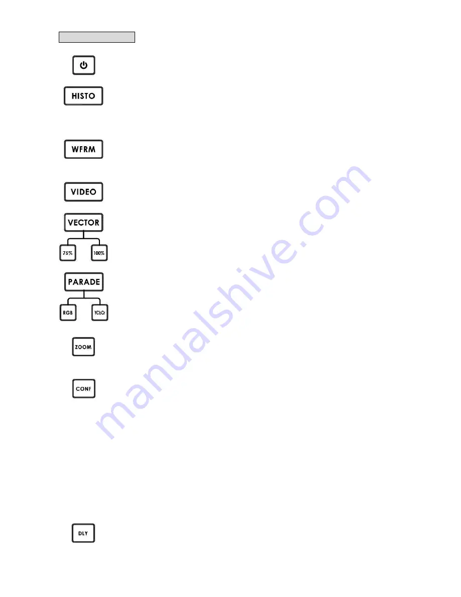
POWER SWITCH
Switches the power On / Off.
HISTOGRAM
HISTOGRAM is used to detect the overall brightness of a location. Through VSM-100 to detect
light sources from all directions reading by the camera, one can individually adjust each
camera to the desired state.
WAVEFORM MONITOR
Waveform monitor is used as a reference to adjust the brightness of a camera. One can
accompany grayscale chart to better distinguish the color level of the adjusting camera.
VIDEO DISPLAY
Display the SDI Input video source.
VECTOR
Applied a 75% or 100% color bar signal.
PARADE CALIBRATION
Parade calibration on RGB or YCbCr mode.
Aim the camera to take the entire test chart as a sample image. This step is necessary to make
sure that the color saturation of an image reproduced from the camera is consistent and does
not tint to any particular color that can cause color cast.
X ZOOM
To adjust the brightness of an area in detail, one can monitor a selected spot by choosing
display graph from 20%~100%.
CONFIGURATION
576i THUMBNAIL
Set the display monitor at the lower left hand corner to 16:9 or 4:3 when the signal is 576i.
SDI LOOPTHROUGH
Set loop through on / off mode
CAPTURE
Set sampling mode FRAME: Capture the entire frame as a sample.
FIELD1: Capture frame 1 as a sample only.
FIELD2: Capture frame 1 as a sample only.
FIRMWARE REVISION
Display current software version
X DELA
This is used by adjusting the position of the matrix.
Set delay time from 0 ~ 17.0235uS
Содержание VSM-100
Страница 1: ...VECTOR SCOPE MONITOR VSM 100 Quick Start Guide www datavideo tek com...
Страница 13: ...12 VSM 100 Output Display...
Страница 24: ...23 Dimension...


