background image


34 


4. 

Color Management System – Calibration Process 

This chapter will discuss the use of Light Illusion's CMS software for color correction.  

Device Setup 

1.


Before starting the calibration process, you need to install and register the CMS software first. 
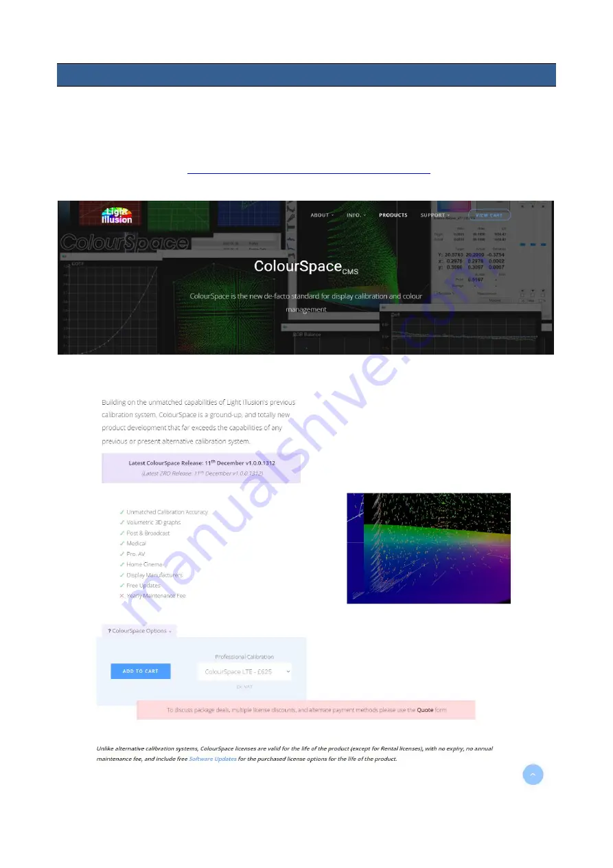
Copy and paste the link 

https://www.lightillusion.com/colourspace.html

 into your browser’s 

address bar then hit enter to open the ColourSpace page shown below. 


Содержание TLM-170FM

Страница 1: ...17 SCOPEVIEW PRODUCTION MONITOR Instruction Manual TLM 170F TLM 170FM TLM 170FR ...

Страница 2: ... PICTURE 17 Brightness 17 Contrast 17 Saturation 17 Tint 17 Sharpness 17 HDMI RGB Range 17 HDMI EDID 17 Color Space 17 Camera Log 18 Def Log 18 User Log 18 Gamma 18 HDR 19 Back Light 19 Color Temperature 19 MARKER 19 Center Marker 20 Center Marker Size 20 Aspect Marker 20 Safety Marker 20 Marker Color 21 Aspect MAT 21 Thickness 21 User Marker H1 H2 21 User Marker V1 V2 21 FUNCTION 21 Scan 21 Aspec...

Страница 3: ...ices The information offered in this instruction manual is intended as a guide only At all times Datavideo Technologies will try to give correct complete and suitable information However Datavideo Technologies cannot exclude that some information in this manual from time to time may not be correct or may be incomplete This manual may contain typing errors omissions or incorrect information Datavid...

Страница 4: ... from the type of power source indicated on the marking label of the AC adapter If you are not sure of the type of power available consult your Datavideo dealer or your local power company 8 Do not allow anything to rest on the power cord Do not locate this unit where the power cord will be walked on rolled over or otherwise stressed 9 If an extension cord must be used with this unit make sure tha...

Страница 5: ...ccident misuse unauthorized repairs sand grit or water is not covered under warranty Viruses and malware infections on the computer systems are not covered under warranty Any errors that are caused by unauthorized third party software installations which are not required by our computer systems are not covered under warranty All mail or transportation costs including insurance are at the expense o...

Страница 6: ...onserve natural resources and ensure that it is recycled in a manner that protects human health and the environment For more information about where you can drop off your waste equipment for recycling please contact your local city office your household waste disposal service or the shop where you purchased the product CE Marking is the symbol as shown on the left of this page The letters CE are t...

Страница 7: ...st and field production applications Features DCI 4K 60p and UHD 4K 60p videos for both input and output 17 monitor with FHD 1920 x 1080 LCD display Supports column YRGB peak time code waveform vector scope audio level meter peaking filter zoom pix to pix overscan check field etc 12G SDI video input with loop through output HDMI 4K input with loop through output Time Code Display LTC VITC Four use...

Страница 8: ...0F SDI Button Press once to enable the SDI video source on the monitor screen You can connect the loop thru port see Rear Panel to a monitor to view the activated input video source As the SDI video source is activated the button LED will be turned ON Dual Color Tally Light Video Source MENU Activation Return EXIT Headphone Audio Volume Control Power ON OFF Shortcut Keys ...

Страница 9: ...menu or increase decrease parameter values using the audio volume adjustment buttons While NOT in the OSD menu pressing either one of the audio volume adjustment buttons will open a Volume slide bar at the bottom of the screen Then press the MENU button to switch to other setting options as listed below Volume Brightness Contrast Saturation Tint Sharpness Exit To adjust the parameter values simply...

Страница 10: ... shortcut key selected at step 1 4 Press the EXIT button to close the pop up function list The pop up function list is shown below Center Marker Aspect Marker Safety Marker Overscan Scan Aspect Color Space Gamma Camera Log Check Field H V Delay Freeze Color Bar False Color Exposure Histogram Waveform Vector Time Code Mute Level Meter Audio Vector Button Reset To reset F1 F4 buttons to factory defa...

Страница 11: ...f SDI and HDMI inputs HDMI Input 1 2 Connect HDMI video and audio source devices HDMI 1 YUV420 not supported HDMI 2 YUV420 supported USB 2 0 Port SERVICE For firmware upgrade only see Firmware Update for more information about firmware upgrade SDI Input Output 1 SDI input output pair DC IN 12V 12 V power input XLR Phoenix Terminal Power ON OFF Switch TLM 170F s main power ON OFF switch SDI Input O...

Страница 12: ...ons Sub Options Parameters Picture Brightness 0 100 Contrast 0 100 Saturation 0 100 Tint 0 100 Sharpness 0 100 HDMI RGB Range Full Limited HDMI EDID 2K 4K Color Space DCI P3 EBU Rec709 SMPTE C Native Camera Log Off Def Log User Log Def Log SLog2ToLC 709 SLog2ToLC 709TA SLog2ToSLog2 709 SLog2ToCine 709 SLog3ToLC 709 SLog3ToLC 709TA SLog3ToSLog2 709 SLog3ToCine 709 ArriLogCTo709 ArriLogCToP3DCI Clog...

Страница 13: ...0 100 Color Temperature 3200 K 5500 K 6500 K 7500 K 9300 K User Color Red Gain 0 255 Green Gain 0 255 Blue Gain 0 255 Red Offset 0 511 Green Offset 0 511 Blue Offset 0 511 Marker Center Marker ON OFF Center Marker Size Small Middle Large Aspect Marker OFF 16 9 1 85 1 2 35 1 4 3 3 2 2 0X 2 0X MAG Grid User Safety Market OFF 95 93 90 88 85 80 ...

Страница 14: ...t Mat OFF 1 2 3 4 5 6 7 Thickness 1 2 3 4 5 6 7 8 9 10 11 12 13 14 15 User Marker H1 1 3840 User Marker H2 1 3840 User Marker V1 1 2160 User Marker V2 1 2160 Function Scan Zoom Aspect Pixel to Pixel Aspect Full 16 9 1 85 1 2 35 1 4 3 3 2 2 0X 2 0X MAG Overscan OFF ON H V Delay Off H V ...

Страница 15: ...30 20 10 Freeze OFF ON Waveform Waveform Multi Y YCbCr RGB OFF Vector OFF ON Transparency 50 25 OFF Peaking OFF ON Peaking Color Red Green Blue White Black Peaking Level 0 100 False Color OFF Default Spectrum ARRI RED False Color Table OFF ON Exposure OFF ON Exposure Level 50 100 IRE Histogram OFF Y RGB ...

Страница 16: ... 2 CH 3 4 CH 5 6 CH 7 8 CH 9 10 CH 11 12 CH 13 14 CH 15 16 Audio Left Out CH1 16 SDI CH 1 8 HDMI Audio Right Out CH1 16 SDI CH 1 8 HDMI System Language English Traditional Chinese Simplified Chinese Color Bar OFF 100 75 Color Bar Mode Rec601 Rec709 BT2020 OSD Timer 10s 20s 30s OSD Transparency OFF 25 50 OSD H Position 0 100 OSD V Position 0 100 Fan Auto ON OFF Color Calibration OFF ON Comparison E...

Страница 17: ...5 PC Monitor RGB Limited 16 235 Standard or HD TVs HDMI EDID The EDID learning function is only used when you experience any failures in playing audio and video correctly You will be able to force the TLM 170F s receiving resolution by setting the EDID to either 2K or 4K so that the connected HDMI source outputs the maximum resolution defined in EDID Color Space Select an option from the list belo...

Страница 18: ...from the list below SLog2ToLC 709 Sony Log format to Rec709 SLog2ToLC 709TA SLog2ToSLog2 709 SLog2ToCine 709 SLog3ToLC 709 SLog3ToLC 709TA SLog3ToSLog2 709 SLog3ToCine 709 ArriLogCTo709 Arri Log format to Rec709 ArriLogCToP3DCI ClogTo709 Canon Log format to Rec709 VLogToV709 Panasonic Log Varicam format to Rec709 JLog To709HLG JVC Log format to Rec709 JLog To709PQ Z7 NLogTo709 Nikon Log format to ...

Страница 19: ... HDR transfer function Back Light Adjust the back light level from 0 100 Color Temperature Select a color temperature for your scene Color temperatures available on the TLM 170F are listed as follows 3200 K 5500 K Desktop publishing or printing 6500 K Usually for ordinary PC use 7500 K 9300 K TV pictures User Color Note Selection of the User Color mode allows you to manually set the color temperat...

Страница 20: ...ze can be set to small medium or large Aspect Marker Sets the aspect marker display at the aspect ratio selected from the list below OFF 16 9 1 85 1 2 35 1 4 3 3 2 2 0X 2 0X MAG Grid User Safety Marker This sets the safety zone display which is the standard viewing range of the recorded video The options are listed as follows OFF 95 93 90 ...

Страница 21: ...ue moves the marker down Function This allows the user to set advanced settings for the TLM 170F such as the scan mode the aspect ratio underscan mode H V delay check field zoom and etc Details of how these functions can be configured are described as follows Scan This sets the Scan mode of the TLM 170F Zoom Enlarge the original image according to the zoom ratio of the TLM 170F Aspect Display the ...

Страница 22: ...e rendered on the display will be larger than the physical area of the screen creating a cropped image on the monitor screen H V Delay Used to monitor the blanking area for H sync and V sync In H delay mode the horizontal sync is delayed so that the horizontal blanking period is displayed on the screen In V delay mode the vertical sync is delayed so that the vertical blanking period is displayed o...

Страница 23: ...usting the brightness contrast saturation tint and sharpness Zoom The zoom function allows you to enlarge the image by a certain percentage 10 90 Note Zoom control is disabled if the scan mode is set to pixel to pixel Freeze The monitor s screen freezes once enabled Waveform The TLM 170F also allows the user to display the image alongside with different monitoring waveforms such as the waveform ve...

Страница 24: ...level Hue The color markers are red magenta blue cyan green and yellow The proximity a signal to one of the markers tells you what color it is Saturation A vectorscope shows you how saturated your color is and how far away the signal is from the center indicates how saturated the color is For example if the color is close to one of those boxes then that means that color in the image is very satura...

Страница 25: ... Opaque Peaking filter The peaking filter once enabled will place color lines on edges of the subject of the focus in the image This function works well if the subject of the focus is correctly exposed for high contrast Red Green Blue White and Black are the five available outline colors on the TLM 170F The Peaking Level determines the sensitivity of the filter Setting the peaking level to a high ...

Страница 26: ...ernal equipment To best utilize this feature you must first understand the color chart below The color chart is like a color scale The exposure level is represented by different colors which correspond to the respective luminance of the pixels as displayed on the monitor The correct exposure ranges from 10 100 Anything below 10 is regarded as underexposed and if exposure exceeds 100 it is deemed o...

Страница 27: ...n yellow and finally to red if overexposed Blue indicates underexposure An example of an original image with the false color applied is shown on the left of the image below The four available false color modes are Default Normal Spectrum ARRI and Red which are illustrated in the diagram below False Color Table This enables disables false color chart on the screen A sample of the chart is shown bel...

Страница 28: ...ll be able to see a zebra pattern superimposed over parts of the image that are exposed to a specific level In this way the exposure of the image displayed on the screen can then be adjusted accordingly on the monitor by changing the exposure level 50 100 IRE ...

Страница 29: ...light than it is to blue or red light Finally the luminosity histogram is produced by counting how many pixels are at each brightness level as shown in the diagram below RGB The RGB histogram is a graph that represents the overall brightness of the entire image In any digital image each individual color is made by combining red green and blue lights with each light represented by its brightness le...

Страница 30: ...ed throughout an image allowing you to evaluate the brightness and exposure of that individual color channel See the diagram below for an example of the color histogram Time Code The TLM 170F is able to decode the following SMPTE timecode formats LTC Linear timecode VITC Vertical interval timecode The decoded time code will be shown at the top of the screen Note Time code is only available with th...

Страница 31: ...DMI mode there will be 8 HDMI embedded audio channels Audio Vector Enable the audio vector scope shown below to view the audio information Audio Vector CH HDMI First enable the audio vector scope then select an audio input channel pair to view the audio information Audio Vector CH SDI First enable the audio vector scope then select an audio input channel pair to view the audio information Audio Le...

Страница 32: ...ect color calibration 7 Switch the standby power mode 8 Reset the entire device s settings Language The available languages are English Traditional Chinese and Simplified Chinese Color Bar Available options are listed as follows OFF disables the color bar 75 or 100 color bar Color Bar Mode The TLM 170F offers three color bar modes listed as follows REC 601 SD video REC 709 HD video BT 2020 4K or 8...

Страница 33: ...n s LightSpace Color Management System CMS which includes a calibration probe and the CMS software The TLM 170F works with CAL PRO and XPT versions only Visit https www lightillusion com lightspace html for more information See the CMS Color Calibration Process in the subsequent chapter Comparison EN By enabling this option you will be able to see the difference between the original image and the ...

Страница 34: ...s CMS software for color correction Device Setup 1 Before starting the calibration process you need to install and register the CMS software first Copy and paste the link https www lightillusion com colourspace html into your browser s address bar then hit enter to open the ColourSpace page shown below ...

Страница 35: ...ro OEM colourimeter Click the link https www lightillusion com murideo_six g html to purchase 4K 8K signal generator Please note that the signal generator is optional 2 Connect the calibration device to the PC or the laptop then the TLM 170F monitor via the HDMI interface Enable Extended Desktop Mode on the PC or the laptop Finally open your graphics control panel to set the HDMI output to Full Ra...

Страница 36: ...30 minutes You can start color calibrating your monitor after you ve completed the device setup Software Setup 1 Select the connected Probe Follow the path Tools Discoverable Probes to access the color calibration devices supported by the CMS Select the color calibration device that is connected to the PC or the laptop The software setup guide will use i1Display Pro OEM for illustrative purposes ...

Страница 37: ...robe and a dialogue box with the message Do you want to connect to i1 Display Pro should pop up Note If the probe model is CA 310 you should see the corresponding model number in the message Click OK if the detected color calibration device is correct 3 Warm up the monitor before calibration Make sure the monitor and the color calibration device are turned ON and leave them running for about 30 mi...

Страница 38: ...CMS User Interface click Tools Calibration Calibration Interface to open the Calibration Interface window then click the Options button to open the window below Locate Patch Scale pane circled in red in the diagram above then enter 16 in min and 235 in max ...

Страница 39: ...nt the probe at the calibration area as close as possible then click the OK button in the dialogue box to start calibration Repeat the process until the MAX value in the Luminance Units pane is in the range of 80 120 Note that the closer the MAX value to 100 the better the TLM 170F is calibrated 6 Color calibration On the Display Characterization window Tools Calibration Display Characterization s...

Страница 40: ...gue box Drag the Calibration Area onto the TLM 170F Lastly enter a name for this particular calibration in the dialogue box point the probe at the calibration area as close as possible then click the OK button to start calibration Please note that it takes approximately one hour to perform 9261 point measurements ...

Страница 41: ...urce pane select Rec709 for the color space and in the Destination pane select the color space generated in the previous step In the Name textbox enter the name of the 3D cube color calibration file The rest of the settings should be configured as shown in the diagram on the left Click Create New button to generate the color conversion data ...

Страница 42: ...n select the 3D DaVinciResolve33 cube format Lastly click the Export button to export the 3D Cube file to a USB thumb drive Settings and file exports of the DCI P3 and BT2020 color spaces are depicted in the diagrams below DCI P3 ...

Страница 43: ...e Insert the USB thumb into the SERVICE port of the TLM 170F and you will be prompted whether to write the 3D CUBE file to the monitor Select Yes to write the 3D Cube file to the monitor The color calibration process is complete after the 3D CUBE file has been written to the monitor successfully Lastly open the TLM 170F s OSD menu select PICTURE User Log then select the 3D CUBE file imported previ...

Страница 44: ... Drive Max 16GB USB A Cable To update the TLM 170F firmware MCU 1 Unzip extract the firmware file 2 Rename the bin file to mcu bin 3 Format the USB 2 0 pen drive to FAT32 4 Copy mcu bin to the USB 2 0 pen drive 5 Power off the TLM 170F On Off Switch at the back of the monitor 6 At the back of the monitor plug the USB 2 0 pen drive into the USB 2 0 port labelled SERVICE 7 Power ON the TLM 170F whil...

Страница 45: ...B 2 0 pen drive into the USB 2 0 port labelled SERVICE on the back of the monitor 5 Load FPGA appears on the screen as soon as the TLM 170F detects the fpga bit file 6 fpga bit is automatically loaded on the TLM 170F 7 The TLM 170F reboots itself after fpga bit is successfully loaded 8 The firmware update is complete if the TLM 170F Monitor reboots successfully ...

Страница 46: ...46 6 Dimensions 單位 毫米 mm ...

Страница 47: ...minal Pitch 5 08mm Standard SDI Signal Format 4096x2160p 23 98 24 25 29 97 30 50 59 94 60 3840x2160p 23 98 24 25 29 97 30 50 59 94 60 4096x2160Psf 23 98 24 25 29 97 30 3840x2160Psf 23 98 24 25 29 97 30 1920x1080p 23 98 24 25 29 97 30 50 59 94 60 1920x1080i 50 59 94 60 1920x1080Psf 23 98 24 25 29 97 30 1280 720p 23 98 24 25 29 97 30 50 59 94 60 525i 625i HDMI Signal Format 4096x2160p 23 98 24 25 29...

Страница 48: ...48 General Operating Temperature 0 C to 40 C 32 F to 104 F Storage Temperature 20 C to 60 C 4 F to 140 F Humidity 10 to 80 non condensing Dimension mm 403 L 305 W 36 6 D Weight 4 1 Kg ...

Страница 49: ...49 Notes ...

Страница 50: ...50 Notes ...

Страница 51: ...51 Notes ...

Страница 52: ...Service and Support www datavideo com product TLM 170F www datavideo com product TLM 170FM www datavideo com product TLM 170KR Datavideo Technologies Co Ltd All rights reserved 2020 Feb 11 2022 Version E1 ...

Отзывы: