

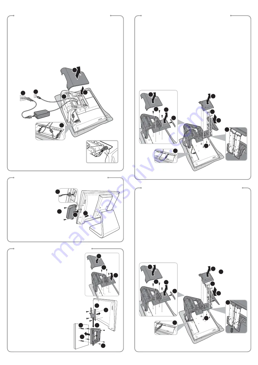
Installing the Power Cord, Power Adapter, and
Network Cable
Installing the Identification Reader (Optional)
Installing the VESA Mount (Optional)
Installing the Customer Display (Optional)
1. Place the Touch Terminal on a soft and
fl
at surface, with the LCD panel facing
down. Remove the cable compartment cover. (a)
2. Connect the network cable to the LAN port. Then connect the power adapter to the
DC IN jack. (b)
3. Route the power adapter and the network cable through the cable compartment. (c)
4. Align and install the cable compartment. (d)
5. Connect the power adapter to the power cord. Then plug the other end of the
power cord to an electrical outlet. (e)
6. Connect the network cable to a hub or switch. (f)
d
e
f
b
a
c
When removing the power adapter, be sure to hold the
end of power adapter
fi
rmly and pull it out.
1. Remove the identi
fi
cation reader
compartment cover. (a)
2. Firmly connect the identi
fi
cation
reader connector into the slot inside
the compartment. (b)
3. Align and install the identi
fi
cation
reader onto its compartment. (c)
4. Secure the identi
fi
cation reader to
the Touch Terminal using the two
screws. (d)
1. Place the Touch Terminal on a soft and
fl
at surface, with the LCD panel facing down.
Remove the cable compartment cover. (a)
2. Remove the four screws on the stand. (b)
3. Remove the stand. (C)
4. Remove the supportive tape from the stand. (d)
5. Remove the four screws on the stand cover. (e)
6. Remove the stand cover. (f)
7. Align and install the customer display into the four threaded stando
ff
s on the stand. (g)
8. Secure the customer display to the stand with the four screw nuts. (h)
9. Route the customer display’s interface cable through the cable guides on the stand
and through the cable compartment as illustrated. (i)
10. Connect the customer display’s interface cable to the RJ-45 COM port on Touch
Terminal. (j)
11. Reverse steps 6 through 1 to complete installing the customer display.
Installing the Secondary LCD Display (Optional)
1. Place the Touch Terminal on a soft and
fl
at surface, with the LCD panel facing down.
Remove the cable compartment cover. (a)
2. Remove the four screws on the stand. (b)
3. Remove the stand. (C)
4. Remove the supportive tape from the stand. (d)
5. Remove the four screws on the stand cover. (e)
6. Remove the stand cover. (f)
7. Align and install the secondary LCD display into the four threaded stando
ff
s on the
stand. (g)
8. Secure the secondary LCD display to the stand with the four screw nuts. (h)
9. Route the secondary LCD display’s power cable and USB cable through the cable
guides on the stand as illustrated. (i)
10. Connect the secondary LCD display’s power cable and USB cable to the corresponding
ports on Touch Terminal. (j)
11. Reverse steps 6 through 1 to complete installing the secondary LCD display.
d
d
d
d
e
e
e
f
f
f
f
g
g
g
h
h
h
i
i
i
j
j
b
b
b
b
a
a
a
a
c
c
c
c
1. Place the Touch Terminal on a soft and
fl
at
surface, with the LCD panel facing down.
Remove the cable compartment cover. (a)
2. Remove the four screws on the stand. (b)
3. Remove the stand. (c)
4. Align and install the mount bracket on the back
of the Touch Terminal. (d)
5. Secure the mount bracket to the Touch Termi-
nal with the four screws. (e)
6. Drill four small holes on the mounting location
and insert the plastic washers into the holes. (f)
7. Align by the screw holes and then install the
wall bracket on the wall. (g)
8. Secure the wall bracket to the wall with the four
supplied screws. (h)
9. Align and hook the Touch Terminal to the wall
bracket, and then push down to secure it into
place. (i)
10. Replace the cable compartment cover for
storing the stand assembly. (a)


