background image


Chapter 1 — Setting Up


5


C

C

o

o

n

n

n

n

e

e

c

c

t

t

i

i

n

n

g

g


t

t

h

h

e

e


P

P

o

o

w

w

e

e

r

r


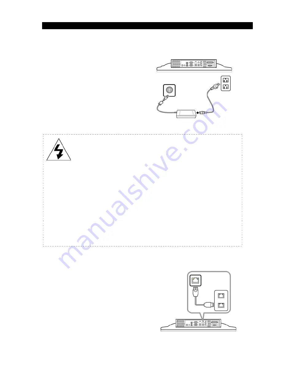
1.


Connect


the


power


cord


to


the


power


adapter.


2.


Connect


the


power


adapter


to


the


Touch


System.


3.


Connect


the


power


plug


to


a


wall


outlet.


CAUTION 

1.


Use


only


the


power


adapter


that


came


with


Touch


System.


Using


other


power


adapters


may


damage


the


unit.


2.


To


avoid


danger,


always


make


sure


that


the


power


cord


is


not


connected


to


a


wall


outlet


before


connecting


the


power


adapter


to


the


Touch


System.


3.


Unplug


the


power


cord


from


the


wall


outlet


before


disconnecting


the


power


adapter


from


the


Touch


System.


4.


When


unplugging,


always


hold


the


plug


head.


Never


pull


on


the


cord.


C

C

o

o

n

n

n

n

e

e

c

c

t

t

i

i

n

n

g

g


t

t

o

o


a

a


N

N

e

e

t

t

w

w

o

o

r

r

k

k


Connect


one


end


of


an


Ethernet


cable


to


the


RJ

45


port


of


the


Touch


System


and


the


other


end


to


network


hub


or


outlet.


Содержание TS-B021\

Страница 1: ...T To ou uc ch h S Sy ys st te em m TS B021 U Us se er r M Ma an nu ua al l V Ve er rs si io on n 1 1 1 1 ...

Страница 2: ......

Страница 3: ... be reproduced in any form by any means without prior written authorization of the manufacturer and its licensors if any S Sa af fe et ty y n no ot ti ic ce es s Notes Keep the packaging box in case the unit needs to be shipped for service Any changes or modifications that do not adhere to the instructions in this manual will void the productʹs warranty Warning Do not attempt to service this unit ...

Страница 4: ...s that products sold into EU countries must have the crossed out trash bin label on the product or the package in some cases As defined by the WEEE directive this cross out trash bin label means that customers and end users in EU countries should not dispose of electronic and electrical equipment or accessories in household waste Customers or end users in EU countries should contact their local eq...

Страница 5: ... Keyboard 4 Connect PS 2 Mouse 4 Connecting the Power 5 Connecting to a Network 5 Chapter 2 6 Using TS B021 6 Front View 6 Side View 6 Rear View 7 I O Ports 8 Hardware Installation 9 Installing the MSR optional 9 Installing the Wireless LAN Module optional 11 Installing the CF Card Reader optional 11 Appendix 12 Technical Information 12 Specifications 12 Frequently Asked Questions FAQ 14 ...

Страница 6: ...e less power and operates with less noise With its simple design it is easy to install and does not take up too much space Economical yet powerful making it the ideal choice for industrial and commercial automation and POI needs P Pa ac ck ka ag ge e C Co on nt te en nt ts s Ensure that the following items are present when you open the box If any of these items are damaged or missing contact your ...

Страница 7: ...1 Screw the 100 100mm VESA mounting bracket to the VESA holes at the back of your Touch System using four M4 10 screws POWER 2 Screw the wall mounting plate to a solid wall 3 Align and hook the mounting bracket onto the wall mounting plate as shown POWER WARNING The wall must be able to support at least 7kg ...

Страница 8: ...ou can connect PS 2 or USB keyboard and mouse to your Touch System C Co on nn ne ec ct t P PS S 2 2 K Ke ey yb bo oa ar rd d Connect the keyboard s PS 2 cable to the purple port of your Touch System C Co on nn ne ec ct t P PS S 2 2 M Mo ou us se e Connect the mouse s PS 2 cable to the green port of your Touch System ...

Страница 9: ...amage the unit 2 To avoid danger always make sure that the power cord is not connected to a wall outlet before connecting the power adapter to the Touch System 3 Unplug the power cord from the wall outlet before disconnecting the power adapter from the Touch System 4 When unplugging always hold the plug head Never pull on the cord C Co on nn ne ec ct ti in ng g t to o a a N Ne et tw wo or rk k Con...

Страница 10: ...F Fr ro on nt t V Vi ie ew w No Item Description 1 Touch screen LCD Provides visual output on a 1920 x 1080 resolution display 2 LED indicator Lights blue when the power is turned on S Si id de e V Vi ie ew w No Item Description 1 USB port Connects to an MSR module or other USB devices 1 2 1 ...

Страница 11: ...eakers Output high quality sounds 2 Brightness button Press to increase the brightness setting of the touch screen monitor 3 Brightness button Press to decrease the brightness setting of the touch screen monitor 4 Power button Press to turn the Touch System on or off 2 3 4 1 1 ...

Страница 12: ...devices using RS 232 serial cables 5 LAN port Connects to a network using an RJ 45 cable 6 Line IN port Use to input audio to the Touch System 7 Line OUT port Connects to external speakers 8 Parallel port Connects to a printer 9 Keyboard port Connects a PS 2 keyboard 10 VGA port Connects to another display monitor 11 USB ports 4 Connects USB peripheral devices 12 MIC IN port Connects to a micropho...

Страница 13: ...g t th he e M MS SR R o op pt ti io on na al l NOTE The module is an optional item and is sold separately To purchase contact your dealer Before setting up the MSR check that the package contains the following items MSR bracket x 1 MSR module x 1 T3 screws x 8 M3 screws x 5 Cable hook x 2 To install the MSR module do the following 1 Remove the stickers from the MSR bracket ...

Страница 14: ...the MSR bracket onto the upper right side of the unit and fasten it with five T3 screws as shown 3 Attach the MSR module to the MSR bracket with two M3 screws as shown 4 Connect the USB cable of the MSR module to the USB port on the unit ...

Страница 15: ... du ul le e o op pt ti io on na al l For added functionality install a wireless LAN module to the Touch System To purchase and install contact your dealer I In ns st ta al ll li in ng g t th he e C CF F C Ca ar rd d R Re ea ad de er r o op pt ti io on na al l For mobility install a CF Card Reader to the Touch System To purchase and install contact your dealer ...

Страница 16: ...uch Screen Resistive USB type System Configuration CPU Intel Atom N270 1 6GHz Fanless Chipset Intel 945GSE ICH7M Main Memory 240 pin DDR2 RAM x 1 slot up to 2GB DDR 667 HDD 1 x 2 5 SATA HDD or SATA DOM Compact Flash Card 1 x Bootable Compact Flash Card socket Type I II I O Ports Parallel Port 1 x LPT Port Serial Port 2 x DB 9 COM Ports USB Port 5 x USB2 0 Ports LAN Port 1 x RJ 45 Port 10 100 1000M...

Страница 17: ...wering System Power Supply DC12V 90W Internal Power Supply AC 100 to 240V Full Range Power Button 1 x Power on off trigger OSD Control 2 x Brightness control button Physical Dimensions Dimension System size 85 L x 513 W x 331 H mm Weight N W 6 5Kg Safety Environment Product Certification CE FCC Operation 0 C to 40 C Operation Humidity 20 to 80 RH OS Compatibility DOS WINDOWS 2000 XP XPE Windows 7 ...

Страница 18: ...ct a keyboard or a mouse into the PS 2 or USB ports Why is the location of the cursor arrow different from the area where I tapped my stylus The screen needs to be re calibrated to ensure accurate results Why can t I connect to a wireless network Check to make sure wireless connection is enabled Your location is out of range of the network Move the computer closer to the access point If the networ...

Отзывы: