


40
HARDWARE INSTALLATION
HARDWARE INSTALLATION
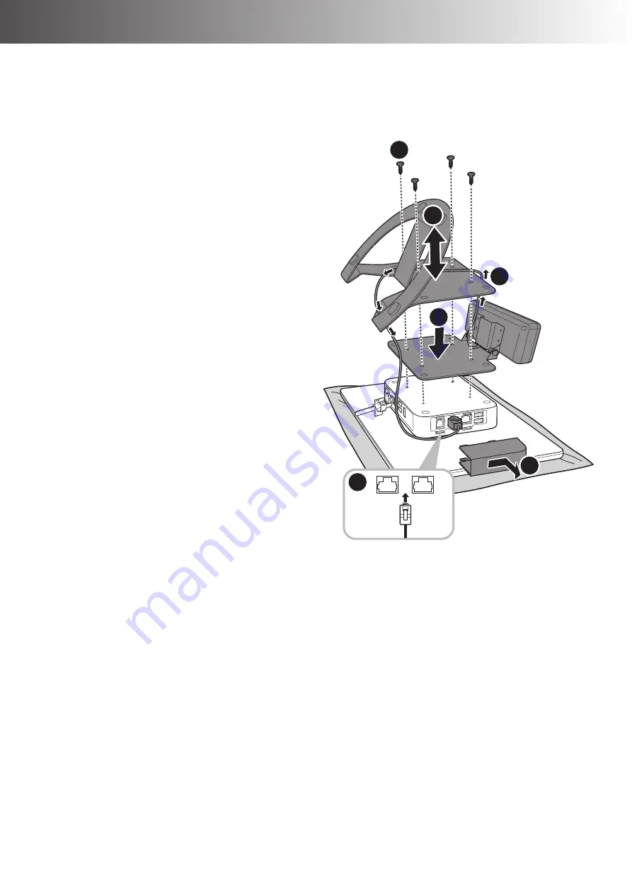
LITE Stand Type
1. Place the Touch Terminal on a soft and flat surface, with the LCD panel facing down.
2. Remove the four screws securing the stand to the Touch Terminal.
(a)
3. Remove the stand.
(b)
4. Detach the I/O port cover.
(c)
5. Align and place the customer
display on the rear of the Touch
Terminal.
(d)
6. Place the stand on the top of the
customer display bracket.
(b)
7. Route the customer display cable as
shown in the illustration.
(e)
8. Connect the customer display cable
to one of the COM ports on the
Touch Terminal.
(f)
9. Replace the I/O port cover.
10. Secure the stand and customer
display bracket to the Touch
Terminal with the four screws.
(a)
a
f
b
d
c
e
Содержание HiFive Series
Страница 1: ...HiFive Series Version 2 0 User Manual...
Страница 7: ...7 Chapter 4 Frequently Asked Questions FAQ 44 Question 1 How do I clear CMOS 44...
Страница 12: ...12 INTRODUCTION Physical Dimensions VESA Mount H 610...
Страница 13: ...INTRODUCTION 13 H 614 H 615...
Страница 14: ...14 INTRODUCTION Standard Display NANO Stand Type H 610 NANO Stand Type H 614...
Страница 15: ...INTRODUCTION 15 LITE Stand Type H 610 LITE Stand Type H 614...
Страница 16: ...16 INTRODUCTION FLEX Stand Type H 610...
Страница 17: ...INTRODUCTION 17 FLEX Stand Type H 614...
Страница 18: ...18 INTRODUCTION FLEX Stand Type H 615...
Страница 19: ...INTRODUCTION 19 VFD Customer Display LITE Stand Type H 610...
Страница 20: ...20 INTRODUCTION LITE Stand Type H 614 FLEX Stand Type H 610...
Страница 21: ...INTRODUCTION 21 FLEX Stand Type H 614...
Страница 22: ...22 INTRODUCTION FLEX Stand Type H 615...
Страница 23: ...INTRODUCTION 23 Secondary LCD Display FLEX Stand Type H 610...
Страница 24: ...24 INTRODUCTION FLEX Stand Type H 614...
Страница 25: ...INTRODUCTION 25 FLEX Stand Type H 615...


