background image

5

Rear View

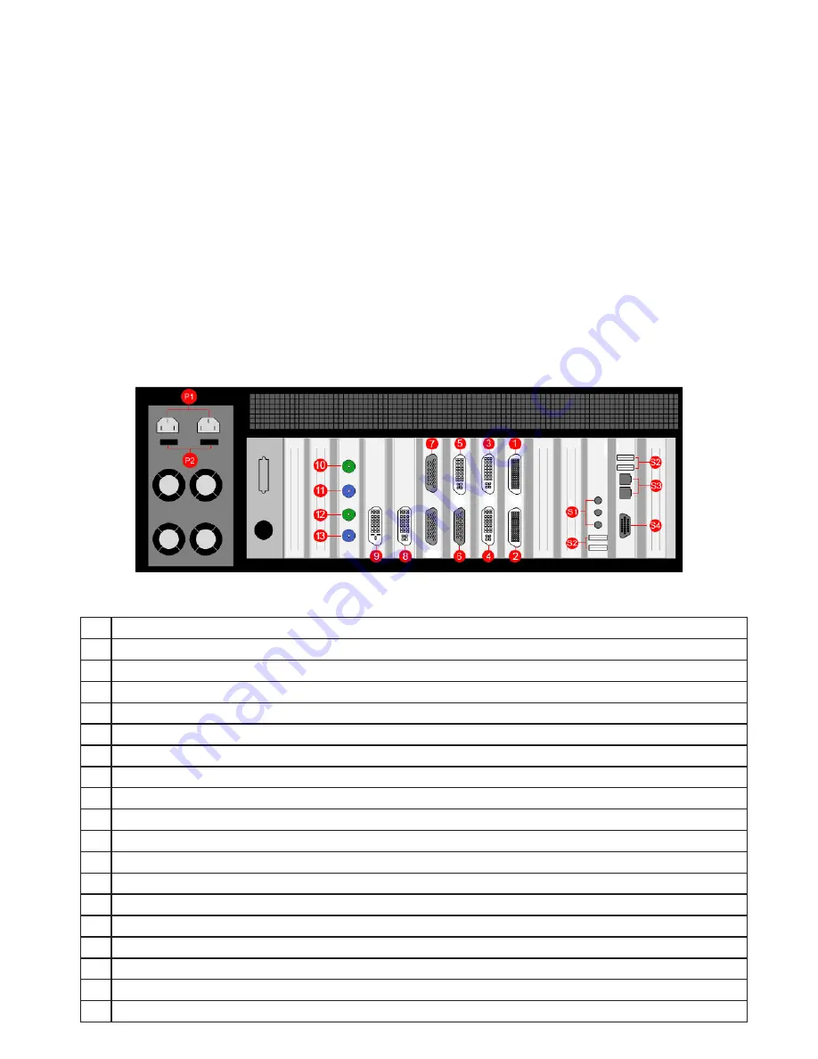
Each custom configured Vision800 will differ depending on the number of output cards and capture cards 
installed.  The illustration below (

Fig.3

) is an example of the rear panel and shows the six types of card that 

may be installed in the Vision800:

• 

Image4 card (outputs 

1

 and 

2

)

• 

VisionRGB-E2S card (inputs 

3

 and 

4

)

• 

Vi1S card (inputs 

5

 and 

6

)

• 

VisionSD8 card (input 

7

)

•          VisionRGB-E1S (inputs 

8

)

• 

VisionDVI-DL card (input 

9

)

• 

VisionSDI2 card Input  (inputs 

10

 and 

12

)

In this example the configuration would support a four screen display wall, (

1

 and 

2

) four RGB/HD/HDMI/

DVI sources (

3, 4, 5

 and 

8

) and a total of twelve SD Composite or S-Video sources, four into the 4 Channel 

SD plus 1 DVI Capture card (

6

) and eight into the VisionSD8 card (

7

), one DVI Dual-Link source (

9

) and two 

SD-SDI/HD-SDI/3g-SDI sources (

10

 and 

12

). 

Fig.3 (Model shown - RPSU)

P1

Power Connectors. (Only one power connector for the ATX model.)

P2

Main Power Switches.  (Only one main power switch on the ATX model.)

1

Image4 graphics card output connector  - For connecting output cables (

Fig.4

)

2

Image4 graphics card output connector -  For connecting output cables (

Fig.4

)

3

VisionRGB-E2S capture card DVI-I Input connector = RGB/HD/HDMI/DVI source.  (

Fig.5/6/7/8

)

4

VisionRGB-E2S capture card DVI-I Input connector = RGB/HD/HDMI/DVI source.   (

Fig.5/6/7/8

)

5

Vi1S capture card DVI-I Input connector – = RGB/HD/HDMI/DVI source.   (

Fig.5/6/7/8

)

6

Vi1S capture card D-Type Input connector = SD Composite/S-Video sources.  (

Fig.11

)

7

VisionSD8 capture card D-Type Input connector = SD Composite/S-Video sources.   (

Fig.12

)

8

VisionRGB-E1S capture card DVI-I Input connector = RGB/HD/HDMI/DVI source.  (

Fig.5/6/7/8

)

9

VisionDVI-DL capture card Dual Link DVI-D Input connector = Dual Link DVI source.  (

Fig.9

)

10

VisionSDI2 capture card BNC Input connector 1 = SD-SDI/HD-SDI/3G-SDI sources.  (

Fig.10

)

11

VisionSDI2 Capture card BNC Passthrough connector for input connector 1.   (

Fig.10

)

12

VisionSDI2 capture card BNC Input connector 2 = SD-SDI/HD-SDI/3G-SDI sources.  (

Fig.10

)

13

VisionSDI2 Capture card BNC Passthrough connector for input connector 2.   (

Fig.10

)

S1

Aux Inputs connectors.

S2

USB Input connectors.

S3

Network connectors.

S4

VGA Output connector for the Control Screen

Key

Содержание Vision800-ATX

Страница 1: ...Vision800 RPSU Vision800 ATX Quick Start Guide Version 1 0 2 ...

Страница 2: ...weisungen dienen derVermeidung von Schäden an Ihrem Datapath Produkt undVerletzungen der Nutzer Bitte lesen Sie sie sorgfältig durch bevor Sie Ihr Produkt in Betrieb nehmen Diese Anweisungen sollten allen Personen zugänglich gemacht werden die mit der Nutzung und der Bedienung von Datapath Produkten betraut sind Stromversorgung Alle Datapath Produkte müssen an die Hauptstromversorgung angeschlosse...

Страница 3: ...ide is designed to aid quick installation and set up of your newVision800 however should you experience any problems not covered in this guide please refer to the online help system Step 1 Packing List Your box should contain Vision800 Chassis Large systems may also include theVision800X expansion chassis See Quick Start Guide appendix supplied Keyboard Mouse Cables Adapters See quantity guide Fig...

Страница 4: ...eVision800 contains additional packaging inside the chassis This MUST be removed prior to operation by removing the chassis lid via the 4 screws 2 located on each side of the case lid Retain packaging materials for future shipping requirements FrontView Fig 2 Key F1 DVDRW drive F2 2 x 500GB removable SATA hard drives F3 Power switch F4 PSU Alarm Reset switch F5 Operating LED s F6 System Reset swit...

Страница 5: ...put connector For connecting output cables Fig 4 2 Image4 graphics card output connector For connecting output cables Fig 4 3 VisionRGB E2S capture card DVI I Input connector RGB HD HDMI DVI source Fig 5 6 7 8 4 VisionRGB E2S capture card DVI I Input connector RGB HD HDMI DVI source Fig 5 6 7 8 5 VisionSD4 1S capture card DVI I Input connector RGB HD HDMI DVI source Fig 5 6 7 8 6 VisionSD4 1S capt...

Страница 6: ...is not re quired Poor handling may cause some pins to bend within the plug on the cable and this in turn will cause damage to the output socket and in some instances will cause irreparable damage to the Printed Circuit Board Such damage is not covered under warranty Control Screen A Control Screen is a stand aloneVGA output screen separate from the display wall The system is configured to boot up ...

Страница 7: ...upplied adapters where required A DVI input is connected directly into the DVI I connector which accepts DVI D digital or DVI A analog inputs Fig 5 An HDMI input is connected to the DVI I connector using the supplied DVI HDMI Adapter Fig 6 A Component input is connected to the DVI I connector using the supplied DVI Component Adapter Fig 7 An RGB VGA input is connected to the DVI I connector using ...

Страница 8: ...sing the supplied Composite S Video Cable Fig 11 A Dual Link DVI input is connected directly into the DVI D Dual Link connector Input cables are not supplied Fig 9 SD SDI HD SDI and a 3G SDI inputs are connected directly into the BNC connector on theVisionSDI2 card Input cables are not supplied Fig 10 ...

Страница 9: ...icated in the table below D Composite or S Video inputs are connected to the D Type Connector on theVisionSD4 1 capture card using the supplied Composite S Video Cable Input Composite S Video Luma BNC Connector Chroma BNC Connector 1 1 9 2 2 10 3 3 11 4 4 12 5 5 13 6 6 14 7 7 15 8 8 16 Fig 12 For Composite input signals into theVisionSD4 1S capture card only the first 4 BNC sockets are used To con...

Страница 10: ...cated on the Operating System CD case in the Accessories pack Once the account has been set up the Control Screen and DisplayWall will open into aWindows desktop TheVision800 has pre configured factory settings for the wall layout and screen resolution These settings can be changed using theTWIN tab accessed from the Display Properties dialog To access theTWIN tab right click on the desktop and se...

Страница 11: ...nge the default factory settings use theTWIN tab to set the number of screens Screen Arrangement and Resolution per Screen Fig 14 Fig 14 Click Apply and then OK In some instances these changes may require a system re start ...

Страница 12: ...ol online help To use theWall Control application locally on theVision800 select Start menu All Programs Wall Control Wall Control My Computer This opens theWall Control application Fig 14 Fig 14 Application Description 1 Control Screen representation 2 DisplayWall representation Displays a snap shot of the display wall including any input sources currently displayed 3 ApplicationToolbar Displays ...

Страница 13: ... Toolbar Fig 14 3 onto the display wall representation Fig 14 2 To move the window drag and drop the window representation to the chosen position on the desktop representation To resize the window click and drag the borders of the window representation Once all the required windows have been placed on the wall the configuration can be saved as a layout file Click on the application File menu and s...

Страница 14: ...een tested to exacting standards in our factory prior to shipping as follows Components Output Cards Dual tested for functionality prior to system build Capture Cards Dual tested for functionality for all input types prior to system build Vision800 Built System Further soak tested for a minimum of 12 hours runningWall Control and a commercial PC stress testing application Date of QATest Authorised...

Отзывы: