background image

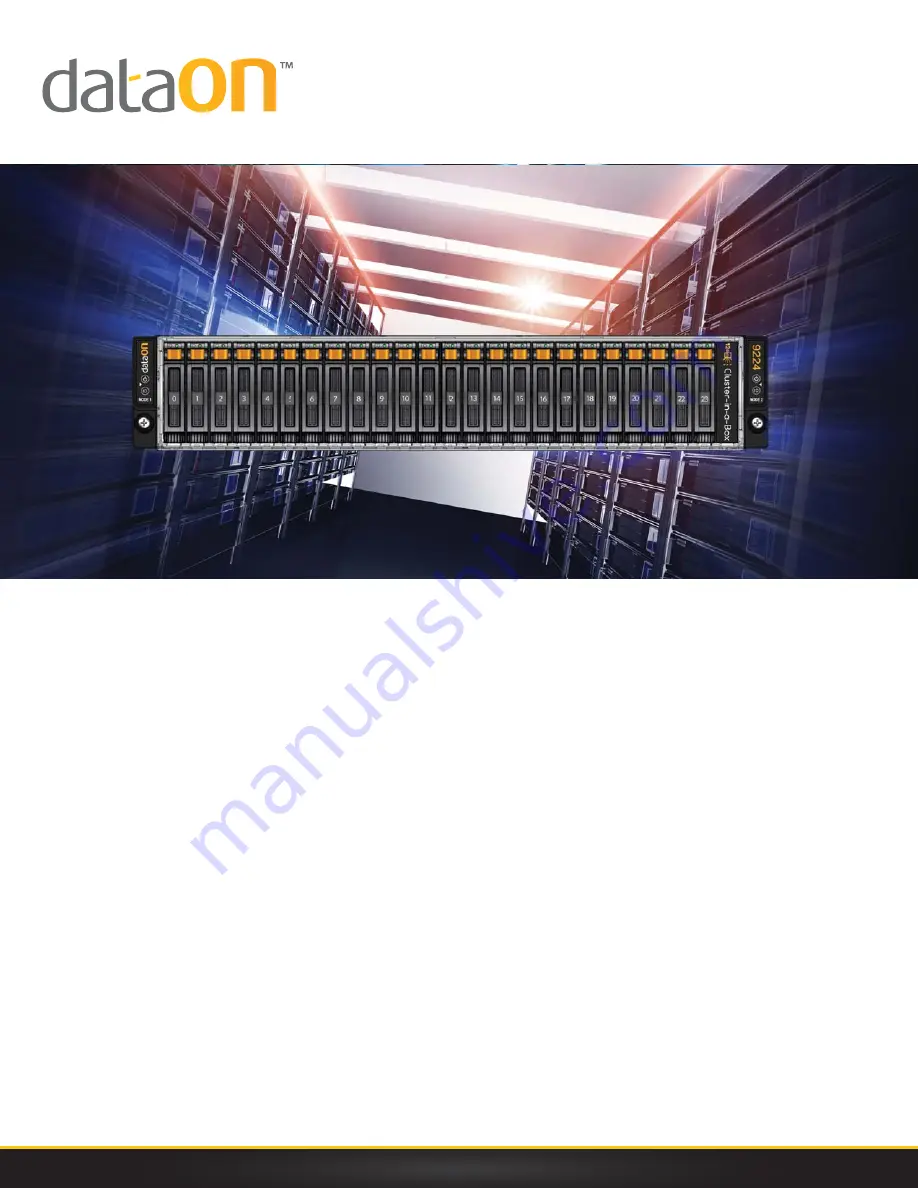
CiB-9224 

V12

Tech Manual

© DataON Storage, storage division of Area Data Systems.

Version   

Jun

. 201

5

Содержание CiB-9224 V12

Страница 1: ...CiB 9224 V12 Tech Manual DataON Storage storage division of Area Data Systems Version Jun 2015...

Страница 2: ...sclaimer This manual provides the information in relation to the set up and installation of the product herein Nothing herein may be construed as granting any right or license relating to any intellec...

Страница 3: ......

Страница 4: ...o install the power supply 2 4 2 4 2 5 SAS HDDs 2 4 2 4 1 To remove a HDD 2 5 2 4 2 To install a HDD 2 6 2 5 Nodes 2 7 2 5 1 To remove the node 2 8 2 5 2 To install the node 2 8 2 6 SAS IO Module 2 8...

Страница 5: ......

Страница 6: ...About This Manual Conventions Safety Symbols Safety Precautions Regulatory and Integration Information Rack Mount Instructions...

Страница 7: ......

Страница 8: ...bols used throughout this manual Warning Information to prevent injury to yourself when trying to complete a task Caution Information to prevent damage to the components when trying to complete a task...

Страница 9: ...isk of injury from electric shock hazards do not open this enclosure Indicates the presence of a hot surface or hot component Warning To reduce the risk of injury from a hot component allow the surfac...

Страница 10: ...ected When in doubt please contact your dealer as soon as possible To avoid short circuits keep all metal object i e Paper clips screws staples etc away from area which might carry electrical current...

Страница 11: ...ot remove the device from the antistatic bag until you are ready to install the device With the device still in its antistatic bag touch it to a metal frame of the system Hold drives by the frame Avoi...

Страница 12: ...old waste Please use the public collection system or return them to the supplier Laser Peripherals or Devices Safety To avoid risk of radiation exposure and or personal injury Do not open the enclosur...

Страница 13: ...environment Such as Clean dry and free of airborne particles other than normal room dust Well ventilated and away from sources of heat including direct sunlight and radiators Vibration or physical sh...

Страница 14: ...rmation Technology Equipment EN 60950 1 Safety of Information Technology Equipment Including Electrical Business Equipment European Committee for Electrotechnical Standardization CENELEC UL 60950 1 Sa...

Страница 15: ...ccordance with the instructions may cause harmful interference to radio communications Operation of this equipment in a residential area is likely to cause harmful interference in which case the user...

Страница 16: ...ower cord must be rated for the product and for the voltage and current marked on the product s electrical ratings label The voltage and current rating of the cord should be greater than the voltage a...

Страница 17: ...sembly the operating ambient temperature of the rack environment may be greater than room ambient Therefore consideration should be given to installing the equipment in an environment compatible with...

Страница 18: ...About This Manual Chapter 1 Introduction Audience Assumptions Manual Organization Specifications Product Features System Overview...

Страница 19: ...al server introduction Hardware Operations Components feature and functions within the system Jumpers and Connectors Reference on system jumpers and connectors Cable Connections Correct cable manageme...

Страница 20: ...tures Chassis 2U rack mounted chassis Power 2 x 1200W redundant power supplies Node Supports 2 nodes Storage 24 x 2 5 hot pluggable HDDs Front 2 x 2 5 SSDs Rear Backplane One 2 5 HDD Backplane Two Boo...

Страница 21: ...iew 1 Power Supply 2 Nodes 3 Power Distribution Boards 4 BBU Assembly BBU Fan Duct 5 Strong Plate 6 Middle Plane 7 Bridge Board 8 Front Panel 2 9 Front Panel 1 10 HDD Bays 11 2 5 HDD Backplane 12 Syst...

Страница 22: ...figurations The 2U server allow front access to the HDD In addition systems LEDs indicators is also located on the front for easy notification Figure 1 3 Front View of 24 x 2 5 HDDs 1 Front Panel 1 2...

Страница 23: ...r Supply 1 2 Power Supply 0 3 Rear Dual USB Port 4 10G NIC 0 Port 5 10G NIC 1 Port 6 Management Port 7 VGA Connector 8 Serial Port 9 ID LED 10 10G NIC 0 Link Activity LED 11 10G NIC 1 Link Activity LE...

Страница 24: ...the front panels of each side The LED indicator provides current system activities and serve as status of system power and ID of each node Figure 1 5 Front Panel Buttons and LEDs 1 ID Button for Node...

Страница 25: ...ormal Red On Hard drive fail or port disable SES Off Normal Purple Blink Rebuild remap SES Blue Purple Blue Purple Blink Consistency check SES Front Panel LED Name Color Condition Function Status Powe...

Страница 26: ...1 5 5 Motherboard Connectors Figure 1 6 Motherboard Overview CiB 9224 V12 1 8...

Страница 27: ...assword Clear Jumper J51 14 Card SGPIO Connector J71 15 DIMM Slots for Processor 0 C0 C1 D0 D1 16 DIMM Slots for Processor 1 A0 A1 B0 B1 17 Backplane Connectors J76 J77 18 Backplane Mini SAS Connector...

Страница 28: ...Chapter 2 Hardware Operations Before You Start Chassis Cover Power Supply 2 5 SAS HDDs Nodes SAS I O Module Boot HDD X16 Riser Card BBU optional System Fans...

Страница 29: ...is fully power off Internal circuity may remain Active Disconnect all power cords from the server to completely power off the system 2 2 Chassis Cover The server is a 2U form factor Designed for c o...

Страница 30: ...e the chassis cover to the right position on the chassis as shown below and then slide it to the front until it is closed Figure 2 2 Sliding the Chassis Cover to the Front Secure the chassis cover wit...

Страница 31: ...The location of power supplies on the server is shown below Figure 2 4 Power Supply Locations Reminder Please follow the steps below before removing or installing the power supply modules Step 1 Disco...

Страница 32: ...lip should snap Connect the AC power cord to the replacement power supply Figure 2 6 Installing the Power Supply 2 4 2 5 SAS HDDs The CiB 9224 V12 support up to 24 x 2 5 hot pluggable SAS HDD SSD You...

Страница 33: ...ray will not fit back into the bay if inserted incorrectly 2 4 1 To remove a HDD SSD Push the release button Pull the lever open Slide the HDD SSD assembly out of the Drive bay Figure 2 8 Sliding out...

Страница 34: ...oving the HDD SSD 2 4 2 To install a HDD SSD Place the HDD SSD to the Drive tray Figure 2 10 Placing the HDD SSD to the Drive Tray Secure the HDD SSD to the Drive tray with four screws Figure 2 11 Fas...

Страница 35: ...e HDD Assembly Make sure that the HDD SSD is connected to the Drive connector on the backplane 2 5 Nodes CiB 9224 V12 system supports two nodes The location of node on the system is shown below Figure...

Страница 36: ...sing the handle Figure 2 14 Removing the Node 2 5 2 To install the node Push the node into the chassis until it s completely seated in place Secure the screw Figure 2 15 Installing the Node 2 6 SAS I...

Страница 37: ...ime Step 2 Disconnect all necessary cables Make sure at least on SAS I O module to provide I O path to HDD SSD 2 6 1 To remove the JBOD Module Pull the lever open Slide the JBOD assembly out of the ch...

Страница 38: ...ou remove or install the Boot SSD please follow the steps below Step 1 Make sure the server is turned off and disconnected to any AC power source Pull the SSD assembly out of SSD cage Figure 2 18 Remo...

Страница 39: ...assembly out of the node Figure 2 20 Removing the Expansion Card Assembly 2 8 2 To remove the expansion Card Loosen the screws that secure the expansion card Remove the expansion card Install the exp...

Страница 40: ...a BBU please follow the steps below Step 1 Make sure the node is turned off Step 2 Remove the node To remove the air duct see 2 5 1 To remove the node Step 3 Disconnect all necessary cables 2 9 1 To...

Страница 41: ...eps above to install the air duct 2 11 System Fans Subdividing the node area and the backplane area is a metal cage that holds the system fans This CiB 9224 V12 contains four system fans which are loc...

Страница 42: ...ed to the AC power Step 2 Remove the chassis cover strong plate To remove the chassis cover see 2 2 Chassis Step 3 Disconnect all the necessary cables 2 11 1 To remove a system fan Lift a system fan o...

Страница 43: ...Type here Appendix China RoHS Regulations...

Страница 44: ...Hardware Operations Appendix Appendix China RoHS Regulations Figure I China RoHS Regulations CiB 9224 V12 I...

Отзывы: