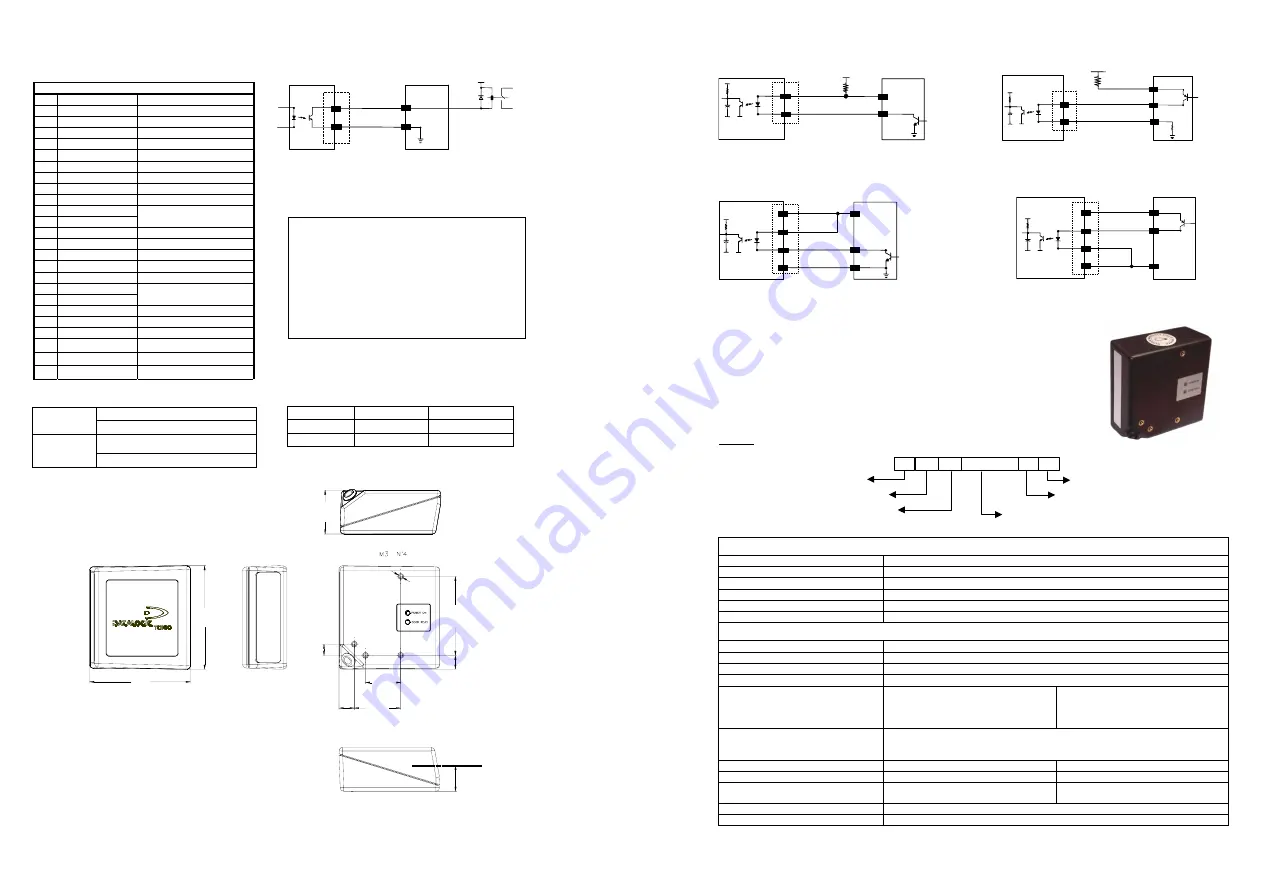
Electrical Connections
25-pin connector
1 Shield
earth
ground
2 TX
transmit
data
3 RX
receive
data
4
RTS
request to send
5
CTS
clear to send
6 nc
not
connected
7 SGND
signal
ground
8
EXT BEEPER
external beeper connection
9 VCC+
+5Vdc
10 nc
not
connected
11 OUT+
12 OUT-
See Figure 1
13 VCC+
+5Vdc
14 nc
not
connected
15 nc
not
connected
16 nc
not
connected
17 nc
not
connected
18 EXT
TRIG+
19 EXT
TRIG-
See Figure 2
20 DATAIN_WAND
21 DATAOUT
22 OUT-
23 CLKIN
24 CLKOUT
25 GND
power
ground
Led Status
ON = Power ON
POWER ON
OFF = Power OFF
ON = Good Read
(the LED will remain ON until status changes)
GOOD READ
OFF = No Read
54
[2
.13]
7.
6
[0.3
0]
30.5
[1.2
0]
31.6
[1.25]
24
[0.94]
9.5
[0.3
7]
10.4
[0.41]
70
.7
[2
.78]
68.6
[2.70]
mm
[in.]
17
.7
[0
.70]
Optical Axis
EXT TRIG+
18
19
+ 5V
TC1100
EXTERNAL TRIGGER
Signal
V
30 Vdc max.
Vext
EXT TRIG-
18
19
+ 5V
TC1100
EXTERNAL TRIGGER
30 Vdc max.
Vext
V
Signal
Ground
EXT TRIG+
EXT TRIG-
Input NPN command using external power
Input PNP command using external power
EXTERNAL TRIGGER
TC1100
Signal
18
19
+ 5V
13
25
GND
Ground
V
EXT TRIG+
EXT TRIG-
Vcc 5Vdc
EXTERNAL TRIGGER
TC1100
18
19
+ 5V
Vcc 5Vdc
13
25
GND
Ground
V
Signal
EXT TRIG+
EXT TRIG-
Input NPN command using TC1100 power
Input PNP command using TC1100 power
Figure 2 - Trigger Connections
Basic Commands for TC1100
The TC1100 default configuration can be changed by receiving commands through the RS232
Interface. The command syntax is given below with an example.
Command syntax
$+
Command(s)
$- <CR>
the new setting will be definitive (stored in FLASH EPROM)
Example:
Baud Rate =
19200
Serial On-Line
Operating Mode
BK0
$-
CR
Carriage return character (0D Hex.)
Exit and save new configuration
AC410132
CD7
Matrix 2/5 3 bars
: no check digit,
variable length code from
1
to
32
characters
$+
Enter configuration environment
Multiple command programming sequence:
Commands:
OPERATING MODES
On-line
BK1
Serial On-line
BK0
Automatic
BK3
Automatic / Lighting System Standby
BK2
To enter in Test mode
#+DStat1<CR>
(does not require $+ or $-)
To exit Test mode
#+DStat0<CR>
(does not require $+ or $-)
GENERAL FEATURES
RS232 interface selection
CP0
RS232 Baud Rate
CD0
for 150 Baud up to
CD8
for 38400 Baud
WEDGE AT
CP500
WEDGE Notebook
CP505
Keyboard Nationality
FJ7
Belgian
FJ4
English
FJ2
French
FJ3
German
FJ1
Italian
FJ6
Spanish
FJ5
Swedish
FJ0
USA
CCD Scan Rate
BT0
67
scans/sec
BT1
135
scans/sec
BT2
270
scans/sec
Puzzle Solver
AU1
enable
AU0
disable
Ink Spread
AX1
enable
AX0
disable
Decoding safety
ED0
1
read
ED1
2
reads
ED2
3
reads
ED3
4
reads
To restore the default configuration
$+$*<CR>
(does not require $-)
To get configuration from the scanner
$+$&<CR>
(does not require $-)
Return to RS232 Interface
Ì$+CP0$-$Î
For WEDGE Users
USER INTERFACE
Vext
40 Vdc max
OUT +
11
12
OUT -
TC1100
Figure 1 - Output Connection (Good Read). Example NPN
Physical Dimensions
Width
70.7 mm
2.78 inches
Length
68.6 mm
2.70 inches
Height
30.5 mm
1.20 inches


