


INSTALLATION
2
2.3.4 DeviceNet
Connector
The 5-pin male connector is only available in the DX8200A DeviceNet model and allows
connection between the host and the reader:
1
3
2
4
5
Figure 27 - DeviceNet 5-pin Male Connector
DX8200A 5-pin DeviceNet connector pinout
Pin Name
Function
2
V +
Supply voltage – positive pin
5
CAN_L
CAN bus data line – L
1 SHIELD
Shield
4
CAN_H
CAN bus data line – H
3
V -
Supply voltage – negative pin
NOTE
The power supplied on pin V+ and V- is used only to propagate power to
the section of the DeviceNet board directly connected to the Bus. It is
completely isolated from the DX8200A power which must be supplied on
pin 9, 13 and pin 23, 25 of the 26-pin Main/Aux connector.
23
Содержание DX8200A
Страница 1: ...DX8200A Reference Manual ...
Страница 2: ......
Страница 3: ...DX8200A REFERENCE MANUAL ...
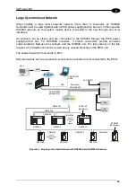
Страница 52: ...DX8200A 2 SC6000 Conveyor Figure 41 Large Synchronized Network Reading Station 36 ...


