background image

DS1100 

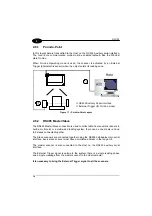
2.6.1 Point-to-Point 

 
In this layout data is transmitted to the Host on the RS232 Auxiliary serial interface.


The Local Echo communication mode must be enabled (default) See the WinHost 
Help On Line. 
 
When On-Line Operating mode is used, the scanner is activated by an External 
Trigger (photoelectric sensor) when the object enters its reading zone.


 RS232 Auxiliary Serial Interface 
 External Trigger (for On-Line mode) 

Figure 17 – Point-to-Point Layout 


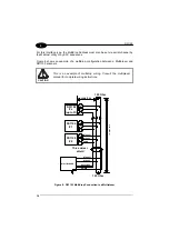
2.6.2 RS485 

Master/Slave 

 
The RS485 Master/Slave connection is used to collect data from several scanners to 
build a multi-point or a multi-sided reading system; there can be one master and up 
to 5 slaves connected together.  
 
The Slave scanners are connected together using the RS485 half-duplex main serial 
interface. Every slave scanner must have a multidrop address in the range 0-4. 
 
The master scanner is also connected to the Host on the RS232 auxiliary serial 
interface. 
 
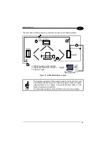
The External Trigger signal is unique to the system; there is a single reading phase 
and a single message from the master scanner to the Host computer. 
 

It is necessary to bring the External Trigger signal to all the scanners. 


18  


Содержание DS1100-1 Series

Страница 1: ...www automation datalogic com DS1100 Reference Manual...

Страница 2: ...ble for technical or editorial errors or omissions contained herein nor for incidental or consequential damages resulting from the use of this material Product names mentioned herein are for identific...

Страница 3: ...3 2 INSTALLATION 4 2 1 Package Contents 4 2 2 Mechanical Installation 5 2 2 1 Mounting DS1100 6 2 2 2 Reading Position 7 2 3 Electrical Connections 8 2 3 1 Power Supply 9 2 3 2 Main Serial Interface...

Страница 4: ...3 3 1 Raster 23 3 4 Reading Diagrams 24 4 MAINTENANCE 26 4 1 Cleaning 26 5 TROUBLESHOOTING 27 5 1 General Guidelines 27 6 TECHNICAL FEATURES 30 GLOSSARY 32 INDEX 36 iv...

Страница 5: ...fer to the WinHost Help On Line SERVICES AND SUPPORT Datalogic provides several services as well as technical support through its website Log on to www datalogic com and click on the links indicated f...

Страница 6: ...manufacture The scanner is classified as a Class 2 laser product according to EN 60825 1 regulations and as a Class II laser product according to CDRH regulations There is a safety device which allows...

Страница 7: ...his device is classified as a class 3B laser product according to EN 60825 1 regulations and as a Class IIIb laser product according to CDRH regulations Any violation of the optic parts in particular...

Страница 8: ...s been tested and found to comply with the limits for a Class A digital device pursuant to part 15 of the FCC Rules These limits are designed to provide reasonable protection against harmful interfere...

Страница 9: ...ERAL VIEW DS1100 1 6 5 4 3 2 8 7 Figure A Laser Beam Output Window TX Data LED Good Read LED Laser On LED Ext Trig LED Power On LED Laser Warning and Device Class Label Mounting Holes 1 2 3 4 5 6 7 8...

Страница 10: ...ling according to the signals necessary for the layout of your application Layout Point to point RS485 Master Slave Multiplexer See sub paragraphs under 2 6 for reference Cabling Power Main Serial Int...

Страница 11: ...ble motor and the laser beam can be switched off through a software command see also Beam Shutter in the WinHost Help On Line 2 serial communication interfaces RS232 RS485 reads all popular codes supp...

Страница 12: ...g POWER ON red indicates the reader is connected to the power supply Figure A 6 EXT TRIG yellow indicates external trigger activity Refer to par 2 3 4 Figure A 5 LASER ON green indicates laser ON stat...

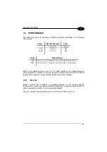
Страница 13: ...n s reading performance Version Max Code Resolution Speed mm mils scans s 1XXX 0 20 8 500 2XXX 0 12 5 500 Version Reading Distance 1XXX 30 mm 1 2 in 220 mm 8 7 in on 0 50 mm 20 mils codes 2XXX 10 mm 0...

Страница 14: ...and all the parts supplied with the equipment are present and intact when opening the packaging the list of parts includes DS1100 reader with cable Quick Reference Guide WinHost CD ROM Barcode test ch...

Страница 15: ...ives all the information required for installation refer to pars 2 2 1 2 2 2 and 2 5 for correct positioning of the scanner with respect to the code passage zone DS1100 mm inch M3 n 3 80 3 15 64 3 2 5...

Страница 16: ...DS1100 2 2 2 1 Mounting DS1100 Using the DS1100 mounting bracket you can obtain the most suitable position for the reader as shown in the figure below Figure 3 Positioning with Mounting Bracket 6...

Страница 17: ...laser beam is emitted from the output window with a 12 2 skew angle This allows installation with minimum overall dimensions 2 Laser Beam DS1100 XXX1 90 Reading Window Position DS1100 XXX0 Direct Read...

Страница 18: ...ps over 0 8 Vdc Figure 5 25 pin Female D sub Connector 25 pin D sub connector pinout Pin Name Function 9 13 VS Power supply input voltage 25 GND Power supply input voltage 1 CHASSIS Chassis Ground 2 2...

Страница 19: ...on protocols It can be used for Multidrop connections in a Master Slave layout or with a Datalogic Multiplexer see par 2 6 2 and 2 6 3 exploiting a proprietary protocol based on polled mode called MUX...

Страница 20: ...configuration between a Multiplexer and DS1100 scanners CAUTION This is an example of multidrop wiring Consult the multiplexer manual for complete wiring instructions max 2 m DS1100 x up to 31 DS1100...

Страница 21: ...ce baud rate data bits etc can be defined using the WinHost utility program or Host Mode Programming installed from the CD ROM The following pins of the 25 pin connector are used to connect the RS232...

Страница 22: ...software Refer to the WinHost Help On Line The yellow LED Figure A 5 is on when EXT TRIG is shorted to GND This input is driven by an NPN type command The connections are indicated in the following di...

Страница 23: ...cond delay An additional 15 ms typical delay can be implemented through a dedicated software parameter refer to WinHost Help On Line 2 3 5 Outputs Two general purpose outputs are available These outpu...

Страница 24: ...trigger is not decoded and OUT2 is associated with the Right event which activates when the code is correctly decoded USER INTERFACE Vext 50 Vdc max 50 mA max DS1100 8 11 12 22 GND Ground Figure 13 D...

Страница 25: ...male connector Pin Name Pin Name 2 RX 3 RX 3 TX 2 TX 5 GND 7 GND 7 RTS 4 RTS 8 CTS 5 CTS How To Build A Simple Interface Test Cable The following wiring diagram shows a simple test cable including po...

Страница 26: ...sition angles Pitch 0 Skew 15 to 30 and Tilt 0 Follow the suggestions for the best orientation The Pitch angle is represented by the value P in Figure 14 Position the reader in order to minimize the P...

Страница 27: ...LAYOUTS The following typical layouts refer to system hardware configurations Dotted lines in the figures refer to optional hardware configurations within the particular layout These layouts also req...

Страница 28: ...The RS485 Master Slave connection is used to collect data from several scanners to build a multi point or a multi sided reading system there can be one master and up to 5 slaves connected together Th...

Страница 29: ...External Trigger Figure 18 RS485 Master Slave Layout NOTE The auxiliary serial port of the slave scanners can be used in Local Echo communication mode to control any single scanner visualize collecte...

Страница 30: ...Trigger for On Line mode Figure 19 Multiplexer Layout The auxiliary serial interface can be used in Local Echo mode to control any single scanner visualize collected data or to configure it using the...

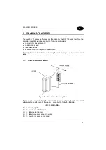
Страница 31: ...should be allowed during the code passage to ensure a successful read 3 1 STEP LADDER MODE Direction of code movement at LS speed DS1100 LH Laser beam Figure 20 Step Ladder Scanning Mode If scanning...

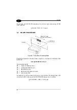
Страница 32: ...f scanning is parallel to the code motion Figure 21 the number of effective scans is given by SN FW LW LS SS 2 These symbols signify SN number of effective scans FW reading field width in mm LW label...

Страница 33: ...mils codes Refer to the diagrams given in par 3 4 for further details on the reading features These diagrams are taken on various resolution sample codes at a 25 C ambient temperature depending on th...

Страница 34: ...2 1 0 1 5 4 3 2 3 4 5 in 0 1 3 2 1 6 in 4 5 7 8 9 0 20 40 60 80 100 120 140 160 180 200 220 240 260 mm 120 100 80 60 40 20 0 20 40 60 80 100 120 mm 0 0 20 mm 8 mils 0 30 mm 12 mils 0 50 mm 20 mils No...

Страница 35: ...20 30 40 50 60 70 80 90 100 110 120 130 mm 60 50 40 30 20 10 0 10 20 30 40 50 60 mm 0 12 mm 5 mils 0 20 mm 8 mils 0 30 mm 12 mils Note 0 0 is the center of the laser beam output window CONDITIONS Code...

Страница 36: ...tc on the windows may alter the reading performance Repeat the operation frequently in particularly dirty environments Use soft material and alcohol to clean the windows and avoid any abrasive substan...

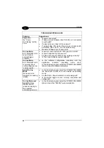
Страница 37: ...lect the parameter you re interested in by pressing the F1 key or select Help Contents DS1100 Configuration from the command menu If you re unable to fix the problem and you re going to contact your l...

Страница 38: ...ector system aligned On line Mode EXT TRIGGER LED is correctly lit but nothing happens no reading results Is the software configuration consistent with the application condition operating mode etc In...

Страница 39: ...transmitting anything to the host Is serial cable connected Is correct wiring respected Are serial host settings equivalent to serial device setting Communication Data transferred to the host are inc...

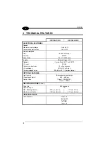
Страница 40: ...0 Vdc Collector current max 50 mA continuous VCE saturation 0 3V at 10 mA max Power dissipation max 200 mW at 40 C Ambient temp OPTICAL FEATURES Light source Semiconductor laser diode Wave length Note...

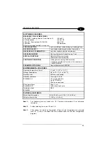
Страница 41: ...serial ports HOST MODE PARAMETER STORAGE Non volatile internal EEPROM ENVIRONMENTAL FEATURES Operating temperature Note 3 0 to 45 C 32 to 113 F Storage temperature 20 to 70 C 4 to 158 F Humidity max 9...

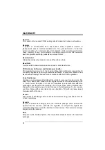
Страница 42: ...in compliance with the CDRH regulations Code Positioning Variation in code placement that affects the ability of a scanner to read a code The terms Pitch Skew and Tilt deal with the angular variations...

Страница 43: ...ly or in pulses It is commonly used as an indicator light and uses less power than an incandescent light bulb but more than a Liquid Crystal Display LCD LEDs have extremely long lifetimes when properl...

Страница 44: ...h as on a Multidrop line Scanner A device that examines a printed pattern barcode and either passes the uninterpreted data to a decoder or decodes the data and passes it onto the Host system Serial Po...

Страница 45: ...hotoelectric sensor or proximity switch which informs the scanner of the presence of an object within its reading zone UPC Acronym for Universal Product Code The standard barcode type for retail food...

Страница 46: ...18 LED Indicators 2 M Main Serial Interface RS485 Half Duplex 9 Maintenance 26 Mechanical Installation 5 Model Description 2 Mounting DS1100 6 O Outputs 13 P Package Contents 4 Performance 23 Picket...

Страница 47: ...ws of Member States relating to electromagnetic compatibility and product safety Bas e sur la l gislation des Etats membres relative la compatibilit lectromagn tique et la s curit des produits ber die...

Страница 48: ...www automation datalogic com DS1100 Reference Manual...

Отзывы: