INSTALLATION
7
2
2.4.1 Power
Supply
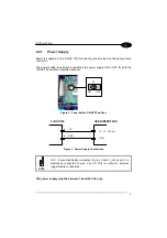
Power is supplied to the C-BOX 100 through the pins provided on the spring clamp
connector.
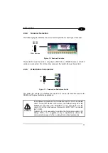
The power switch (see Figure 6) switches the power supply ON or OFF for both the
C-BOX 100 and the connected scanner.
S1
ON
OFF
Figure 6 - Power Switch ON/OFF Positions
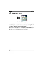
C-BOX 100
1
2
VS
GND
USER INTERFACE
GND
V+ (10 - 30 Vdc)
Figure 7 - Power Supply Connections
NOTE
Pin 1 is also electrically connected to pins 3 and 5, just as pin 2 is
electrically connected to pins 4 and 6. This is useful for external
trigger/inputs connections.
The power supply must be between 10 and 30 Vdc only.
Содержание C-BOX 100
Страница 1: ...C BOX 100 Installation Manual...
Страница 2: ...C BOX 100 Installation Manual...
Страница 3: ...C BOX 100 INSTALLATION MANUAL...
Страница 10: ...viii...


