background image

PRODUCT REFERENCE GUIDE   167

GLOSSARY

AIM

(Association for Automatic Identification and Mobility): AIM Global is the international 
trade association representing automatic identification and mobility technology solu-
tion providers.

AIM DPM Quality Guideline

Standard applicable to the symbol quality assessment of direct part marking (DPM) per-
formed in using two-dimensional bar code symbols. It defines modifications to the mea-
surement and grading of several symbol quality parameters.

Barcodes (1D Codes)

A pattern of variable-width bars and spaces which represents numeric or alphanumeric 
data in machine-readable form. The general format of a barcode symbol consists of a 
leading margin, start character, data or message character, check character (if any), stop


character, and trailing margin. Within this framework, each recognizable symbology 
uses its own unique format.

BIOS

Basic Input Output System. A collection of ROM-based code with a standard API used to


interface with standard PC hardware.

Bit

Binary digit. One bit is the basic unit of binary information. Generally, eight consecutive 
bits compose one byte of data. The pattern of 0 and 1 values within the byte determines 
its meaning.

Bits per Second (bps)

Number of bits transmitted or received per second.

Bright Field Illumination

Lighting of surfaces at high (narrow) angles used to provide maximum reflection of the 
light to the reader’s lens. This is effective on surfaces that absorb light or are not highly 
reflective and also on low contrast codes.

Содержание 937800000

Страница 1: ...Matrix 120 PRODUCT REFERENCE GUIDE Image Based Reader ...

Страница 2: ...documentation and shall ensure that all notices appear on any reproductions of the documentation Electronic versions of this document may be downloaded from the Datalogic website www datalogic com If you visit our website and would like to make comments or suggestions about this or other Datalogic pub lications please let us know via the Contact page Disclaimer Datalogic has taken reasonable measu...

Страница 3: ...SB Connections 2 Serial Connections 3 CBX100 CBX500 Pinout for Matrix 120 4 Step 2 Mount and Position the Reader 5 Step 3 X PRESS Configuration 6 Focus Aiming 6 Setup 7 Learn 7 Reset Reader to Factory Default Environment Optional 8 Step 4 Installing DL CODE Configuration Program 9 Step 4A Ethernet Device Discovery 10 Step 4B USB Device Discovery 13 Step 4C Serial Device Discovery 15 Step 5 Device ...

Страница 4: ...Supply 56 Main Serial Interface 56 RS232 Interface 56 RS422 Full Duplex Interface 57 Inputs 58 External Trigger Input Connections Using Matrix 120 Power 60 External Trigger Input Connections Using External Power 62 Input 2 Connections Using Matrix 120 Power 63 Input 2 Connections Using External Power 64 Outputs 65 Output 1 and 2 Connections Using Matrix 120 Power 66 Output 1 and 2 Connections Usin...

Страница 5: ... 124 Moving code out of the Field of View 125 Multi Image Acquisition Settings 126 Automatic Image Settings Selection 127 External Image Settings Selection 128 Image Cropping 132 Direct Part Marking Applications 137 Pass Through Configurations 138 USB HID Keyboard Wedge Configurations 140 Backup and Restore Through DL CODE 142 Backup 143 Restore 144 Replacement 144 Restore Defaults 145 Restore Def...

Страница 6: ...sing the reader TECHNICAL SUPPORT Support Through the Website Datalogic provides several services as well as technical support through its website Log on to www datalogic com For quick access from the home page click on the search icon and type in the name of the product you re looking for This allows you access to download Data Sheets Manu als Software Utilities and Drawings Hover over the Suppor...

Страница 7: ... Support An excellent source for technical assistance and information is an authorized Datalogic reseller A reseller is acquainted with specific types of businesses application software and computer systems and can provide individualized assistance ...

Страница 8: ...oduct with essential requirements listed in the applicable European directive Since the directives and applicable standards are subject to continuous updates and since Datalogic promptly adopts these updates therefore the EU declaration of conformity is a living document The EU declaration of conformity is available for competent authorities and customers through Datalogic commercial reference con...

Страница 9: ...his equipment in a residential area is likely to cause harmful interference in which case the user will be required to correct the interference at his her own expense EAC COMPLIANCE Customs Union The CU Conformity certification has been achieved this allows the Product to bear the Eurasian Mark of conformity LED SAFETY LED emission according to EN 62471 LASER SAFETY All Matrix 120 readers contain ...

Страница 10: ...installed however it is also a precision product and therefore before and during installation it must be handled correctly to avoid damage avoid that the scanners hit one another causing damage They should be handled separately avoid that the readers are dropped exceeding shock limits do not fine tune the positioning by striking the reader or bracket ...

Страница 11: ...PRODUCT REFERENCE GUIDE XI do not weld the reader into position which can cause electrostatic heat or reading window damage do not spray paint near the reader which can cause reading window damage ...

Страница 12: ... Connector 7 Internal Illuminator 2 Ethernet Cable w Connector 8 Aiming System Laser Source 3 Ethernet Connection LED 9 Lens 4 HMI X PRESS Interface 10 Good Read LED green 5 Power On LED 11 Focus Adjustment Screw 6 Bracket Mounting Holes 4 GENERAL VIEW XII MATRIX 120 GENERAL VIEW ...

Страница 13: ...wer On LED 6 Lens 2 HMI X PRESS Interface 7 Good Read LED green 3 Bracket Mounting Holes 4 8 Power Serial Interface I O Cable w Connector 4 Internal Illuminator 9 Focus Adjustment Screw 5 Aiming System Laser Source PRODUCT REFERENCE GUIDE XIII ...

Страница 14: ...GENERAL VIEW XIV MATRIX 120 ...

Страница 15: ...t from the Matrix 120 on board Ethernet interface by using a CAB ETH M0x cable There is no need to use a crossover adapter since Matrix 120 incorporates an autocross function Matrix 120 power and I O device connections take place through the CBX connection box using the CAB 1011 accessory cable When One Shot or Phase Mode Operating mode is used the reader is activated by an External Trigger photoe...

Страница 16: ...stem in a USB point to point configuration you need the hardware indicated in Figure 2 In this layout the data is transmitted to the Host from the Matrix 120 USB interface by using a CAB 1021 accessory cable Matrix 120 Host CAB 1021 Figure 2 USB Point to Point Layout ...

Страница 17: ...erating mode is used the reader is activated by an External Trigger photoelectric sensor when the object enters its reading zone Host Main Serial Interface RS232 or RS422 Full Duplex Optional Outputs External Trigger for One Shot or Phase Mode CAB 1011 CBX 10 30 Vdc External Power for Matrix 120 and I O Accessories Figure 3 Serial Point to Point Layout NOTE For device configuration through DL CODE...

Страница 18: ...Ground O1 Output 1 O1 Output 1 Inputs 02 Output 2 V Power Source External Trigger O2 Output 2 I1A External Trigger A polarity insensitive O3A Output 3 CBX500 only I1B External Trigger B polarity insensitive V Power Reference External Trigger Auxiliary Interface V Power Source Inputs Matrix 120 has no Auxiliary Interface I1A Input 2 A polarity insensitive I2B Input 2 B polarity insensitive V Power ...

Страница 19: ... into consideration these three ideal label position angles Pitch or Skew 10 to 20 and Tilt 0 although the reader can read a code at any tilt angle provided the code fits into the Field Of View FOV FOVV FOVH No Pitch Tilt or Skew Pitch Minimize Tilt any angle inside FOV Skew assure at least 10 Figure 5 Pitch Skew and Tilt References CAUTION Do not connect GND and SGND to different external ground ...

Страница 20: ...p reset or restart phase all the LEDs blink for one second On the connector side of the reader near the cable the POWER ON LED blue indicates the reader is correctly powered 2 Enter the Focus Aim function by pressing and holding the X PRESS push button until the Aim LED is on 3 Release the button to enter the Aim function The aiming system turns on see 4 Place an application specific code in front...

Страница 21: ...nd in this case Matrix 120 emits a long low pitched beep Figure 8 X PRESS interface Setup function 1 Enter the Learn function by pressing and holding the X PRESS push button until the Learn LED is on 2 Release the button to enter the Learn function The Learn LED will blink until the procedure is completed The Learn procedure ends when the Image Processing and Decoding parame ters are successfully ...

Страница 22: ...the Default configuration is set as the startup configuration NOTE The Grade A Barcode Test Chart cannot be used to set the Code 128 sym bology even though the reader successfully reads the code Use the application specific code if you need to set this symbology When using X PRESS or the BM150 menu to perform Auto Learn only a single code can be configured successive Learns will substitute the cur...

Страница 23: ...n program and follow the installation proce dure NOTE NOTE 2 When the installation is complete the DL CODE entry is created in the Start Pro grams bar under Datalogic as well as a desktop icon Double click the desktop icon to run it Depending on your Matrix 120 model you can connect to DL CODE configuration envi ronment through one of the following interfaces Model Interface Instructions Matrix 12...

Страница 24: ...ray see Figure 10 1 First the device must be added to the LAN by aligning its IP Address to the net work The network administrator should provide valid LAN address es 2 Find your device in the list by matching its serial number SN then click on the device wrench icon to open the Device Environment Configuration window 3 Change the Ethernet Settings IP Address Subnet Mask Gateway Address etc accord...

Страница 25: ...PRODUCT REFERENCE GUIDE 11 Figure 11 Device Environment Configuration Window 4 Click OK the device will reappear in the list of Online Devices in color meaning it is now part of the LAN and can be configured The new IP address will also be dis played ...

Страница 26: ...ag the device icon into the Selected Device Information Area Details about the device will be displayed in this area Figure 12 DL CODE Opening Window NOTE After device discovery configure your device through DL CODE as described in Step 5 Device Configuration ...

Страница 27: ...on to discover it The unit will be shown in the network Online Devices list Matrix 120 devices connected through the USB interface will not be shown in the Serial Devices list 2 Find your device in the list by matching its serial number SN The USB driver cre ates a virtual Ethernet connection with an IP address that cannot be modified In fact it is easy to see the unit in the list because it is th...

Страница 28: ...e click on or drag the device icon into the Selected Device Information Area Details about the device will be displayed in this area NOTE After device discovery configure your device through DL CODE as described in Step 5 Device Configuration ...

Страница 29: ...ited when using this interface It is always advised to use the Ethernet interface whenever possible If you re not sure of the Serial baud rate you can also check the Enable Automatic Device Discovery box which for serial devices will try com munication at all baud rates but only at No parity 8 data bits 1 stop bit Enabling this parameter can notably lengthen Discovery time therefore in general it ...

Страница 30: ...etting Started icon 6 Open the Serial devices tab and double click on or drag the device icon into the Selected Device Information Area The device is now connected to the DL CODE Configuration environment Configure your device through DL CODE as described in Step 5 Device Configuration ...

Страница 31: ...des Enabled Filters CODE 128 EAN 128 CODE 39 CODE 93 CODABAR PDF417 MICRO PDF417 GS1 DATABAR GS1 DATABAR STACKED GS1 DATABAR LIMITED GS1 DATABAR EXPANDED GS1 DATABAR EXPANDED STACKED UPCEAN FAMILY EAN13 UPCEAN FAMILY EAN8 UPCEAN FAMILY UPCA UPCEAN FAMILY UPCE DATAMATRIX ECC 200 QR MICRO QR AZTEC MAXICODE DOTCODE ERODE 3x3 5x5 and 7x7 DILATE 3x3 5x5 and 7x7 SMOOTHING Advanced Setup provides access ...

Страница 32: ...ont of the reader at the correct application reading distance The Matrix 120 models are factory calibrated at three focus positions 45 70 and 125 mm for WVGA models 45 80 and 125 mm for MP models Using a 2 5 mm Hex key Allen wrench rotate the Focus Adjustment Screw at the back of the reader to one of these three positions for your application Refer to the Reading Diagrams in Reading Features start...

Страница 33: ...correct reading conditions Static or Dynamic Tuning 1D or 2D code Include Image Filtering to find the best decoding condition If the image display area is too dark to see the images being captured you can drag the Gain and Exposure Time sliders circled in red in the figure above to the right to increase visibility This will not affect Auto matic Setup ...

Страница 34: ... procedure The reader begins acquiring images At the end of the procedure the Status Completed message appears You can Close the Automatic Setup window Your reader is now optimized for decoding Continue with the Reading Phase configura tion described on page 25 ...

Страница 35: ...e and begins acquir ing images 3 Place an application specific code in front of the reader at the correct application reading distance The Matrix 120 models are factory calibrated at three focus positions 45 70 and 125 mm for WVGA models 45 80 and 125 mm for MP models Using a 2 5 mm Hex key Allen wrench rotate the Focus Adjustment Screw at the back of the reader to one of these three positions for...

Страница 36: ...MATRIX 120 4 Once positioned stop image acquisition by clicking on the Pause button 5 Click the Image Settings branch and then click the Image Auto Setup button to automatically acquire the best exposure time and gain values ...

Страница 37: ...3 6 Select the Static or Dynamic Self Tuning option Start Autolearn and Apply to the Image Settings NOTE For applications having multiple lighting or code reading conditions up to 10 different Image Settings can be configured by adding them with the icon ...

Страница 38: ...he Code Settings with the Delete icon If you don t know the code type you can use the Code Autolearn feature by click ing on the Code Autolearn icon 1 See the DL CODE User s Manual for details 9 For each code symbology set the relative parameters according to your applica tion NOTE The large green box for each symbol indicates the code localization area which by default is equal to the maximum FoV...

Страница 39: ...ing Mode from the icons over the Configu ration Parameters tree area Continuous One Shot or Phase Mode 2 Configure the relative Operating Mode parameters from the Reading Phase parameters panel Different groups will appear in the panel depending on the selected icons over the Configuration Parameters tree area ...

Страница 40: ...de Combination By default the Expected Codes when more than one code type is selected are in logical AND which means that all codes are required to be decoded to produce a Good Read condition 2 If a Good Read condition should be produced when any single code is decoded independent of the others then they need to be combined in logical XOR To do this drag the code icon s from their relative Expecte...

Страница 41: ...cific Data Formatting Message s from the Configu ration Parameters tree area Message 1 Message 2 etc You can add fields to the output message by clicking on the icons above the Message Field area They will be appended to the message You can drag them to position them between other fields in the message so that the output message is ordered according to your application requirements Each field has ...

Страница 42: ...ure your application specific Digital Output s and Green Red Spots if used from the Configuration Parameters tree area Output 1 Output 2 etc NOTE Save the configuration from temporary memory to permanent memory overwriting the previously saved configuration ...

Страница 43: ... to enter the Test function Once entered the Bar Graph on the five LEDs is activated and if the reader starts reading codes the Bar Graph shows the Good Read Rate Figure 13 X PRESS Interface Test Function 3 To exit the Test press the X PRESS push button once NOTE The Bar Graph has the following meaning Figure 14 Test Function Bar Graph In case of No Read condition only the STATUS LED red is on and...

Страница 44: ...ced product configuration refer to the DL CODE User s Guide available in the DL CODE Help menu Host Mode Programming The reader can also be partially configured from a host computer using the Host Mode programming procedure See the Host Mode Programming Manual on the DL CODE mini DVD zip file ...

Страница 45: ...e of use because of DL CODE configuration software X PRESS button and intuitive HMI The Matrix 120 is the entry level model of the best in class Matrix family of high perfor mance industrial 2D imagers The Matrix 120 is the perfect solution when small dimension simple integration and performance are the key drivers This makes the Matrix 120 the ideal product for OEM customers Chemical Biomedical i...

Страница 46: ...y Embedded Ethernet connectivity SerialandUSBoptionsonthesamemodel ESD versions for electronic applications DL CODE software configurator for outstanding ease of setup X PRESS Datalogic s GreenSpot technologyandintuitiveHMI fortopeaseofuse Top industrial grade IP65 operating temperatures 0 45ºC 32 113ºF Sulfur Gas Protection according to ISO EN 60068 2 43 ...

Страница 47: ... Figure 15 4 TRIGGER yellow LED indicates the status of the reading phase Figure 15 5 COM yellow LED indicates active communication on the main serial port Figure 15 6 STATUS red LED indicates a NO READ result Figure 15 7 When connected to a Fieldbus network through the CBX500 the COM LED is always active even in the absence of data transmission because of polling activity on the Fieldbus network ...

Страница 48: ...configure pho tometry parameters Learn to self detect and auto configure for read ing an unknown barcode by type and length Only one symbology type can be saved using this method Performing Autolearn on a second sym bology will overwrite the first one X PRESS Functions Quick access to the following functions is provided by an easy procedure using the push button 1 Press the button the Status LED w...

Страница 49: ...rms Image Acquisition parameter calibra tion for the specific code presented to it The Setup LED will blink until the procedure is completed The Setup procedure ends when the Image Acquisition parameters are successfully saved in the reader memory the Setup LED will stop blinking and Matrix 120 emits 3 high pitched beeps If the calibration cannot be reached after a timeout of about 5 five seconds ...

Страница 50: ... function at any time by pressing the X PRESS push button once After a short delay the Learn procedure is canceled Diagnostic Indication The STATUS red and READY green LEDs blink simultaneously to signal the pres ence of an error Diagnostic message transmission on interfaces can be enabled to pro vide details about specific error conditions See the Diagnostic Error Conditions chart in the Diagnost...

Страница 51: ...SCRIPTION Matrix 120 readers are described by their model number which indicates the charac teristics listed in the diagram below Not all combinations are available For a complete list of combinations see the Models tab on the Product page of the website ...

Страница 52: ...SER USB WA 937800009 MATRIX 120 311 010 1 2MP SER ETH WA 937800010 MATRIX 120 311 100 1 2MP SER USB WA 1D 937800011 MATRIX 120 311 110 1 2MP SER ETH WA 1D 937800014 MATRIX 120 311 005 1 2 SER USB WA PLZR 937800015 MATRIX 120 311 015 1 2 SER ETH WA PLRZ 937800045 MATRIX 120 310 01A 1 2MP SER ETH 937800052 MATRIX 120 210 050 WVGA SER USB STD SC 937800053 MATRIX 120 210 060 WVGA SER ETH STD SC 937800...

Страница 53: ... 1534 02 Adapter Cable Ethernet M12 to female RJ45 93A050057 Connectivity CBX100 Compact Connection Box 93A301067 CBX500 Modular Connection Box 93A301068 Various Fieldbus Host Interface Modules are available Various Fieldbus Host Interface Modules and All In One Connection Box Kits are available BA100 DIN Rail Adapters 93ACC1821 BA200 Bosch and 80 20 Profile Adapters 93ACC1822 Various M12 Service ...

Страница 54: ...rix Symbology for Automated Mail Processing Deformed or Overprinted Code Reading Matrix 120 assures the reading of deformed and or overprinted codes even though damaged or printed on high reflective surfaces see Figure 17 Figure 18 and Figure 19 Figure 17 Unidose Flow Pack with PDF417 Code Figure 18 Overprinted Barcode Readable by Matrix 120 also Through the Envelope Window Film Figure 19 Barcode ...

Страница 55: ...ective and or Colored Surface Matrix Wide Angle Polarizer models provide advantages in particular applications which require codes to be read very short reading distances on reflective and or colored sur faces like black plastic and have 0 Skew angles WA Polarizer Model Reading Reflective Label Standard Model Reading Reflective Label CAUTION Matrix 120 readers are not designed to be used in real t...

Страница 56: ...printed material This enables easy reliable optical capture without interfer ing with design aesthetics Figure 22 Digimarc Barcode distributed on all sides of the packaging DWCODE is the name that GS1 US and GS1 Germany use to describe a Digimarc Bar code data carrier A DWCODE includes the Global Trade Item Number GTIN i e a glob ally unique number used to identify trade items products or services...

Страница 57: ...imarc technology and application examples download our Digimarc Technical Note from Datalogic website For quick access from the home page click on the search icon and type in Digimarc This allows you access to download Data Sheets Manuals and everything related to Digimarc Barcode ...

Страница 58: ...0 reader and all the parts supplied with the equipment are present and intact when opening the packaging the list of parts includes Matrix 120 reader Quick Reference Guide Focus Lock Labels 5 Mounting Kit Mounting Screws 5 Washers 5 5 Mounting Brackets 1 Figure 24 Package Contents ...

Страница 59: ...the reader are for mechanical fixture Figure 25 The diagrams below give the overall dimensions of the reader and may be used for its installation Refer to page 50 for various mounting solutions and correct positioning and Chapter 6 Reading Features for FOV vs Reading Distance considerations mm in Optical Axis Figure 25 Overall Dimensions of Matrix 120 Ethernet Models ...

Страница 60: ...mm in Optical Axis INSTALLATION 46 MATRIX 120 Figure 26 Overall Dimensions of Matrix 120 Ethernet Models with ESD Cover ...

Страница 61: ...mm in Optical Axis MECHANICAL DIMENSIONS PRODUCT REFERENCE GUIDE 47 Figure 27 Overall Dimensions of Matrix 120 USB Models ...

Страница 62: ...mm in Optical Axis INSTALLATION 48 MATRIX 120 Figure 28 Overall Dimensions of Matrix 120 USB Models with ESD Cover ...

Страница 63: ...mm in MECHANICAL DIMENSIONS PRODUCT REFERENCE GUIDE 49 Figure 29 Mounting Bracket Overall Dimensions ...

Страница 64: ... 120 Using the Matrix 120 mounting brackets you can obtain rotation on the various axes of the reader as shown in the following illustrations Skew Pitch Figure 30 Bottom Mounting Positions for USB Models Figure 31 Bottom Mounting Positions for Ethernet Models ...

Страница 65: ...Tilt Skew MOUNTING AND POSITIONING MATRIX 120 PRODUCT REFERENCE GUIDE 51 Figure 32 Side Mounting Positions for USB Models Figure 33 Side Mounting Positions for Ethernet Models ...

Страница 66: ...gle The Pitch Skew and Tilt angles are represented in Figure 34 Follow the suggestions below for the best orientation Position the reader in order to avoid the direct reflection of the light emitted by the Matrix 120 reader it is advised to assure at least 10 for the Skew angle No Pitch Tilt or Skew Pitch Minimize Tilt any angle inside FOV Skew assure at least 10 Figure 34 Code Reading Orientation...

Страница 67: ...OV vs Reading Distance considerations FOCUS LOCK LABEL OPTIONAL There are five single use focus lock labels included in the packaging that can be use to protect the focus position from being changed after the application has been com pleted These are adhesive labels that are designed to be applied over the focus screw as shown in the figure below ...

Страница 68: ... sub connector on the CBX side We recommend making system connections through one of the CBX connection boxes since they offer the advantages of easy connection easy device replacement opto iso lated inputs External Trigger and Input 2 and outputs Outputs 1 and 2 and filtered reference signals NOTE CAUTION Do not use CAB DSxx S accessory cables with Matrix 120 If you require direct wiring to the r...

Страница 69: ...Input 2 B polarity insensitive V Power Reference Inputs Outputs V Power Source Outputs V Power Reference Outputs O1 Output 1 opto isolated and polarity sensitive O1 Output 1 opto isolated and polarity sensitive O2 Output 2 opto isolated and polarity sensitive O2 Output 2 opto isolated and polarity sensitive Auxiliary Interface Matrix 120 has not Auxiliary Interface ID NET Matrix 120 has no ID NET ...

Страница 70: ...arameters baud rate data bits etc can be defined by the user via DL CODE software For more details refer to the Help On Line page of the Reading Phase step Channels in DL CODE Details regarding the connections and use of the interfaces are given in the next para graphs This interface can also be used for configuration through DL CODE see Step 4C Serial Device Discovery RS232 Interface The RS232 in...

Страница 71: ... point to point connections over longer distances max 1200 m 3940 ft than those acceptable for RS232 communications or in electrically noisy environments The CBX pinout follows CBX100 500 Description TX RS422 Transmit Data RX RS422 Receive Data TX RS422 Transmit Data RX RS422 Receive Data SGND Signal Ground Figure 38 RS422 Full Duplex Connections NOTE For applications that do not use RS422 transmi...

Страница 72: ...e Match Code option is enabled The electrical features of both inputs are VAB 30 Vdc max IIN 12 mA CAB 1011 12 mA CBX max The active state of these inputs are selected in software An anti disturbance filter by default is implemented in software on both inputs The value can be changed through the software parameter Debounce Filter See the Help On Line page of the Reading Phase step Inputs in DL COD...

Страница 73: ... External Trigger I1A External Trigger A polarity insensitive I1B External Trigger B polarity insensitive V Power Reference External Trigger The yellow Trigger LED Figure 15 5 is on when the active state of the External Trigger corresponds to ON Polarity insensitive inputs assure full functionality even if pins A and B are exchanged ...

Страница 74: ... Power Figure 40 PNP External Trigger Using Matrix 120 Power CAUTION Power from the Vdc GND spring clamps is available directly to the Input Device on the V V spring clamps and does not pass through the Power Switch ON OFF inside the CBX Disconnect the power supply when working inside the CBX ...

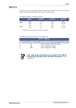
Страница 75: ...INPUTS PRODUCT REFERENCE GUIDE 61 Figure 41 NPN External Trigger Using Matrix 120 Power ...

Страница 76: ...ctions Using External Power Figure 42 PNP External Trigger Using External Power Figure 43 NPN External Trigger Using External Power CBX100 500 Description V Power Source Inputs I2A Input 2 A polarity insensitive I2B Input 2 B polarity insensitive V Power Reference Inputs ...

Страница 77: ...Using Matrix 120 Power Figure 45 NPN Input 2 Using Matrix 120 Power CAUTION Power from the Vdc GND spring clamps is available directly to the Input Device on the V V spring clamps and does not pass through the Power Switch ON OFF inside the CBX Disconnect the power supply when working inside the CBX ...

Страница 78: ...CBX ELECTRICAL CONNECTIONS 64 MATRIX 120 Input 2 Connections Using External Power Figure 46 PNP Input 2 Using External Power Figure 47 NPN Input 2 Using External Power ...

Страница 79: ... PD 90 mW Max 50 C ambient temp By default Output 1 is associated with the No Read event which activates when the code s signaled by the external trigger are not decoded and Output 2 is associated with the Good Read event which activates when all the selected codes are correctly decoded The output signals are fully programmable being determined by the configured Activa tion Deactivation events Dea...

Страница 80: ...tput Using Matrix 120 Power Figure 49 NPN Open Collector Output Using Matrix 120 Power CAUTION Power from the Vdc GND spring clamps is available directly to the Out put Device on the V V spring clamps and does not pass through the Power Switch ON OFF inside the CBX Disconnect the power supply when working inside the CBX ...

Страница 81: ...er Figure 50 PNP Open Emitter Output Using External Power Figure 51 NPN Open Collector Output Using External Power CAUTION If output devices are powered externally separate from Matrix 120 power it is always advised to maintain the same voltage levels used for the Matrix 120 device ...

Страница 82: ...ernet interface the following communication channels are available TCP Client TCP Server UDP Channel FTP Client The following Fieldbus protocols are also available over the on board Ethernet inter face EtherNet IP PROFINET IO Modbus TCP Client For further details refer to the Help On Line page of the Reading Phase step Channels and Fieldbuses in DL CODE USER INTERFACE SERIAL HOST The following tab...

Страница 83: ... to a local host by using a CAB ETH M0x cable There is no need to use a crossover adapter since Matrix 120 incorporates an autocross function 10 30 Vdc Host Matrix 120 CAB ETH M0x CBX Ethernet Interface Auxiliary Serial Interface Data Monitor External Trigger for One Shot or Phase Mode CAB 1011 External Power for Matrix 120 and I O Accessories CAUTION Matrix 120 readers do not have Auxiliary Seria...

Страница 84: ...work LAN one or more Matrix 120 readers can be con nected to the network by using CAB ETH M0x cables Host Matrix 120 CAB ETH M0x Ethernet Interface Main Serial Interface Data Monitor External Trigger for One Shot or Phase Mode CBX CBX Switch 10 30 Vdc CAB 1011 Power Figure 53 Ethernet Network Layout ...

Страница 85: ...face selection to monitor data When One Shot or Phase Mode operating mode is used the reader can be activated by an External Trigger for example a pulse from a photoelectric sensor when the object enters its reading zone Host CAB 1011 Matrix 120 CBX Main Serial Interface RS232 or RS422 Full Duplex Optional outputs External Trigger for One Shot or Phase Mode 10 30 Vdc External Power for Matrix 120 ...

Страница 86: ...ters its reading zone Fieldbus Host Matrix 120 CBX500 with Fieldbus Interface Profibus DeviceNet etc Other I O devices External Trigger for One Shot or Phase Mode 10 30 Vdc Power CAB 1011 Host Interface Module Fieldbus Figure 55 Fieldbus Interface Point to Point Layout CAUTION Matrix 120 readers do not have Auxiliary Serial interfaces Therefore neither data monitoring nor device configuration ca b...

Страница 87: ...IP Server 2 Main Serial Interface RS232 or RS422 Full Duplex Pass through Input Channel Output Channel Switch Mode Continuous Mode External Trigger 10 30 Vdc power Figure 56 Pass Through Layout In a Pass through layout each device supports multiple pass through configurations to accept input from different devices on different channels i e middle reader above How ever readers are not required to h...

Страница 88: ... different operating mode Continuous One Shot Phase Mode etc USB CONNECTION For Matrix 120 xxx x0x models the USB connection is possible in different layouts Host CAB 1021 Matrix 120 Figure 57 USB Point to Point Layout NOTE USB HID Keyboard Wedge configurations can also be made through this interface See USB HID Keyboard Wedge Configurations on page 140 ...

Страница 89: ...lows I O devices to be connected to the reader when using the USB interface Matrix 120 Host CAB 1051 I O I O External Power only for I O Accessories 5 30 Vdc for inputs 5 Vdc for outputs Figure 59 USB Point to Point Layout with I O The electrical connections between I O devices and CAB 1051 together with the rela tive Matrix 120 Line Type parameter settings are shown below Inputs Outputs Vext 5 30...

Страница 90: ...TYPICAL LAYOUTS 76 MATRIX 120 Vout 3 3 Vdc max Iout 50 mA max CAB 1051 Input 1 Trigger orange Input 2 gray GND black CAB 1051 Output 1 purple Output 2 red white GND black Inputs Outputs ...

Страница 91: ...al Min Reading Distance mm Matrix 120 210 xxx WVGA 8 mm 39 26 46 25 Matrix 120 310 XXX MP 8 mm 41 32 49 30 Matrix 120 311 xxx MP WA 8 mm 52 40 63 30 The viewing angle has a tolerance of 1 depending on the reading distance FOVx 2 d d0 tan ax 2 where FOVx horizontal vertical or diagonal FOV αx horizontal vertical or diagonal viewing angles d reading distance in mm from window surface to code surface...

Страница 92: ...NG FEATURES 78 MATRIX 120 Figure 60 Reading Distance References Example The FOV for a Matrix 120 310 xxx at a reading distance of 100 mm is FOVH 2 100 mm 8 mm tan 41 2 81 mm FOVV 2 100 mm 8 mm tan 32 2 62 mm ...

Страница 93: ...ifferent from the FOV See the Reading Diagrams starting on page 84 for specific reading area examples Matrix 120 210 xxx WVGA Models 1D Codes Figure 61 Global FOV 1D Code Diagram for WVGA Models The following diagrams are given for typical performance at 25 C using high quality grade A symbols according to ISO IEC 15416 1D code and ISO IEC 15415 2D code print quality test specifications Testing sh...

Страница 94: ...READING FEATURES 80 MATRIX 120 2D Codes Figure 62 Global FOV 2D Code Diagram for WVGA Models Matrix 120 310 xxx MP Models 1D Codes Figure 63 Global FOV 1D Code Diagram for MP Models ...

Страница 95: ...GLOBAL FOV DIAGRAMS PRODUCT REFERENCE GUIDE 81 2D Codes Figure 64 Global FOV 2D Code Diagram for MP Models ...

Страница 96: ...READING FEATURES 82 MATRIX 120 Matrix 120 311 xxx MP WA Models 1D Codes Figure 65 Global FOV 1D Code Diagram for MP Models 2D Codes Figure 66 Global FOV 2D Code Diagram for MP Models ...

Страница 97: ...GLOBAL FOV DIAGRAMS PRODUCT REFERENCE GUIDE 83 Matrix 120 310 xxA Models Digimarc Barcode ...

Страница 98: ...0 75 The reading distance ranges are measured from the reading window surface Common software parameter settings reading all 1D code symbologies Processing Mode Standard reading 2D code symbologies Processing Mode Standard Code Contrast Low Decoding Complexity Medium When defining a HW SW configuration for the Matrix 120 for conditions differ ent from those of the reference diagrams it is suggeste...

Страница 99: ...ix 120 210 xxx WVGA Code 128 0 12 mm 5 mils Conditions Hardware Settings Code Symbology Code 128 Code Resolution 0 12 mm 5 mils Tilt Angle 0 Skew Angle 15 Focusing Distance mm 45 70 Software Parameters Exposure Time μs 400 500 Gain 10 15 Illuminator Lighting Very High Power Strobed ...

Страница 100: ...ils Conditions Hardware Settings Code Symbology Code 128 Code Resolution 0 20 mm 8 mils Tilt Angle 0 Skew Angle 15 Focusing Distance mm 45 70 125 Software Parameters Exposure Time μs 400 500 600 Gain 15 20 30 Illuminator Lighting Very High Power Strobed ...

Страница 101: ...m 10 mils Conditions Hardware Settings Code Symbology Code 128 Code Resolution 0 25 mm 10 mils Tilt Angle 0 Skew Angle 15 Focusing Distance mm 45 70 125 Software Parameters Exposure Time μs 500 700 800 Gain 10 20 32 Illuminator Lighting Very High Power Strobed ...

Страница 102: ...ils Conditions Hardware Settings Code Symbology Code 128 Code Resolution 0 33 mm 13 mils Tilt Angle 0 Skew Angle 15 Focusing Distance mm 45 70 125 Software Parameters Exposure Time μs 400 600 800 Gain 10 20 32 Illuminator Lighting Very High Power Strobed ...

Страница 103: ...ffect of the lens the reading area is limited to the central zone of the Ver tical Field of View Figure 67 WVGA Model Vignetting Effect Depending on the application Image Cropping can be applied above and below the central zone of the vertical FOV limiting image acquisition to the effective reading area and therefore increasing frame rate and reducing overall image processing time ...

Страница 104: ... Matrix 0 12 mm 5 mils Conditions Hardware Settings Code Symbology Data Matrix ECC 200 Code Resolution 0 12 mm 5 mils Tilt Angle 0 Skew Angle 15 Focusing Distance mm 45 Software Parameters Exposure Time μs 450 Gain 5 Illuminator Lighting Very High Power Strobed ...

Страница 105: ...mm 7 5 mils Conditions Hardware Settings Code Symbology Data Matrix ECC 200 Code Resolution 0 19 mm 7 5 mils Tilt Angle 0 Skew Angle 15 Focusing Distance mm 45 70 Software Parameters Exposure Time μs 450 500 Gain 5 10 Illuminator Lighting Very High Power Strobed ...

Страница 106: ...ware Settings Code Symbology Data Matrix ECC 200 Code Resolution 0 25 mm 10 mils Tilt Angle 0 Skew Angle 15 Focusing Distance mm 45 70 125 Software Parameters Exposure Time μs 280 500 650 Gain 10 10 13 Illuminator Lighting Very High Power Strobed Decoding Complexity Very High ...

Страница 107: ...0 310 xxx MP Code 128 0 12 mm 5 mils Conditions Hardware Settings Code Symbology Code 128 Code Resolution 0 12 mm 5 mils Tilt Angle 0 Skew Angle 15 Focusing Distance mm 45 80 125 Software Parameters Exposure Time μs 300 350 500 Gain 10 15 20 Illuminator Lighting Very High Power Strobed ...

Страница 108: ...ils Conditions Hardware Settings Code Symbology Code 128 Code Resolution 0 20 mm 8 mils Tilt Angle 0 Skew Angle 15 Focusing Distance mm 45 80 125 Software Parameters Exposure Time μs 300 500 700 Gain 15 20 25 Illuminator Lighting Very High Power Strobed ...

Страница 109: ...m 10 mils Conditions Hardware Settings Code Symbology Code 128 Code Resolution 0 25 mm 10 mils Tilt Angle 0 Skew Angle 15 Focusing Distance mm 45 80 125 Software Parameters Exposure Time μs 300 400 500 Gain 10 15 25 Illuminator Lighting Very High Power Strobed ...

Страница 110: ...ils Conditions Hardware Settings Code Symbology Code 128 Code Resolution 0 33 mm 13 mils Tilt Angle 0 Skew Angle 15 Focusing Distance mm 45 80 125 Software Parameters Exposure Time μs 400 600 700 Gain 15 20 32 Illuminator Lighting Very High Power Strobed ...

Страница 111: ...ffect of the lens the reading area is limited to the central zone of the Ver tical Field of View Figure 68 MP Model Vignetting Effect Depending on the application Image Cropping can be applied above and below the central zone of the vertical FOV limiting image acquisition to the effective reading area and therefore increasing frame rate and reducing overall image processing time ...

Страница 112: ...trix 0 076 mm 3 mils Conditions Hardware Settings Code Symbology Data Matrix ECC 200 Code Resolution 0 076 mm 3 mils Tilt Angle 0 Skew Angle 15 Focusing Distance mm 45 Software Parameters Exposure Time μs 250 Gain 10 Illuminator Lighting Very High Power Strobed ...

Страница 113: ... mils Conditions Hardware Settings Code Symbology Data Matrix ECC 200 Code Resolution 0 12 mm 5 mils Tilt Angle 0 Skew Angle 15 Focusing Distance mm 45 80 125 Software Parameters Exposure Time μs 250 300 600 Gain 15 15 15 Illuminator Lighting Very High Power Strobed ...

Страница 114: ...Conditions Hardware Settings Code Symbology Data Matrix ECC 200 Code Resolution 0 19 mm 7 5 mils Tilt Angle 0 Skew Angle 15 Focusing Distance mm 45 80 125 Software Parameters Exposure Time μs 250 380 600 Gain 15 20 20 Illuminator Lighting Very High Power Strobed ...

Страница 115: ... mils Conditions Hardware Settings Code Symbology Data Matrix ECC 200 Code Resolution 0 25 mm 10 mils Tilt Angle 0 Skew Angle 15 Focusing Distance mm 45 80 125 Software Parameters Exposure Time μs 280 700 1000 Gain 15 20 32 Illuminator Lighting Very High Power Strobed ...

Страница 116: ... 311 xxx MP WA Code 128 0 10 mm 4 mils Conditions Hardware Settings Code Symbology Code 128 Code Resolution 0 10 mm 4 mils Tilt Angle 0 Skew Angle 15 Focusing Distance mm 45 80 Software Parameters Exposure Time μs 250 300 Gain 10 15 Illuminator Lighting Very High Power Strobed ...

Страница 117: ... 0 12 mm 5 mils Conditions Hardware Settings Code Symbology Code 128 Code Resolution 0 12 mm 5 mils Tilt Angle 0 Skew Angle 15 Focusing Distance mm 45 80 Software Parameters Exposure Time μs 250 400 Gain 10 12 Illuminator Lighting Very High Power Strobed ...

Страница 118: ...ils Conditions Hardware Settings Code Symbology Code 128 Code Resolution 0 20 mm 8 mils Tilt Angle 0 Skew Angle 15 Focusing Distance mm 45 80 125 Software Parameters Exposure Time μs 300 400 600 Gain 10 20 25 Illuminator Lighting Very High Power Strobed ...

Страница 119: ...mm 10 mils Conditions Hardware Settings Code Symbology Code 128 Code Resolution 0 25 mm 10 mils Tilt Angle 0 Skew Angle 15 Focusing Distance mm 45 80 125 Software Parameters Exposure Time μs 400 600 700 Gain 10 20 25 Illuminator Lighting Very High Power Strobed ...

Страница 120: ...ils Conditions Hardware Settings Code Symbology Code 128 Code Resolution 0 33 mm 13 mils Tilt Angle 0 Skew Angle 15 Focusing Distance mm 45 80 125 Software Parameters Exposure Time μs 400 600 700 Gain 10 20 25 Illuminator Lighting Very High Power Strobed ...

Страница 121: ... effect of the lens the reading area is limited to the central zone of the Ver tical Field of View Figure 69 MP Model Vignetting Effect Depending on the application Image Cropping can be applied above and below the central zone of the vertical FOV limiting image acquisition to the effective reading area and therefore increasing frame rate and reducing overall image processing time ...

Страница 122: ... Matrix 0 13 mm 5 mils Conditions Hardware Settings Code Symbology Data Matrix ECC 200 Code Resolution 0 12 mm 5 mils Tilt Angle 0 Skew Angle 15 Focusing Distance mm 45 Software Parameters Exposure Time μs 250 Gain 10 Illuminator Lighting Very High Power Strobed ...

Страница 123: ...mm 7 5 mils Conditions Hardware Settings Code Symbology Data Matrix ECC 200 Code Resolution 0 19 mm 7 5 mils Tilt Angle 0 Skew Angle 15 Focusing Distance mm 45 80 Software Parameters Exposure Time μs 200 400 Gain 10 12 Illuminator Lighting Very High Power Strobed ...

Страница 124: ...Conditions Hardware Settings Code Symbology Data Matrix ECC 200 Code Resolution 0 25 mm 10 mils Tilt Angle 0 Skew Angle 15 Focusing Distance mm 45 80 125 Software Parameters Exposure Time μs 250 450 600 Gain 10 15 20 Illuminator Lighting Very High Power Strobed ...

Страница 125: ...rix 120 311 xxx MP WA PLRZ Code 128 0 12 mm 5 mils Conditions Hardware Settings Code Symbology Code 128 Code Resolution 0 12 mm 5 mils Tilt Angle 0 Skew Angle 0 Focusing Distance mm 45 80 Software Parameters Exposure Time μs 600 800 Gain 25 32 Illuminator Lighting Very High Power Strobed ...

Страница 126: ...ignetting applies to the F125 position for WA models Conditions Hardware Settings Code Symbology Code 128 Code Resolution 0 20 mm 8 mils Tilt Angle 0 Skew Angle 0 Focusing Distance mm 45 80 125 Software Parameters Exposure Time μs 700 1000 1000 Gain 25 32 32 Illuminator Lighting Very High Power Strobed ...

Страница 127: ...ter 6 Vignetting applies to the F125 position for WA models Conditions Hardware Settings Code Symbology Code 128 Code Resolution 0 25 mm 10 mils Tilt Angle 0 Skew Angle 0 Focusing Distance mm 45 80 125 Software Parameters Exposure Time μs 700 1000 1000 Gain 25 32 32 Illuminator Lighting Very High Power Strobed ...

Страница 128: ...ect of the lens the reading area is limited to the central zone of the Ver tical Field of View Figure 70 MP Model Vignetting Effect Depending on the application Image Cropping can be applied above and below the central zone of the vertical FOV limiting image acquisition to the effective reading area and therefore increasing frame rate and reducing overall image processing time ...

Страница 129: ...PLRZ Data Matrix 0 13 mm 5 mils Conditions Hardware Settings Code Symbology Data Matrix ECC 200 Code Resolution 0 12 mm 5 mils Tilt Angle 0 Skew Angle 15 Focusing Distance mm 45 Software Parameters Exposure Time μs 600 Gain 24 Illuminator Lighting Very High Power Strobed ...

Страница 130: ... mils Conditions Hardware Settings Code Symbology Data Matrix ECC 200 Code Resolution 0 19 mm 7 5 mils Tilt Angle 0 Skew Angle 15 Focusing Distance mm 45 80 Software Parameters Exposure Time μs 600 900 Gain 25 30 Illuminator Lighting Very High Power Strobed ...

Страница 131: ...5 mm 10 mils Conditions Hardware Settings Code Symbology Data Matrix ECC 200 Code Resolution 0 25 mm 10 mils Tilt Angle 0 Skew Angle 0 Focusing Distance mm 45 80 Software Parameters Exposure Time μs 600 900 Gain 25 30 Illuminator Lighting Very High Power Strobed ...

Страница 132: ...an be calculated as follows X Texp min LS max Texp min is the minimum Exposure Time value obtainable for the specific application It can be evaluated in static reading conditions and depends on the Matrix reader model selected for the application internal lighting system optical lens reading distance and on any external lighting system It may also depend on code printing quality and reader positio...

Страница 133: ...s reflective transparent coverings different supports and printing techniques Code Resolution maximum speed increases when decreasing code resolution i e 2X There is a decrement of overlapping effects between two adjacent ele ments Tilt Angle maximum speed decreases when increasing Tilt angle from 0 to 45 degrees The Internal Lighting parameter allows setting the operating mode of the internal lig...

Страница 134: ...however you will use DL CODE connecting to the reader through the on board Ethernet interface See Chapter 1 Steps 5 6 DL CODE SYSTEM REQUIREMENTS To install and run DL CODE you should have a Laptop or PC that meets or exceeds the following 2 00 GHz or faster microprocessor Windows XP SP3 7 8 or 10 1 GB RAM 2 GB hard disk for 64 bit machines 1 GB hard disk for 32 bit machines 100 Base T Ethernet On...

Страница 135: ...lways good practice to peri odically save the configuration to permanent memory Save on Device to avoid losing the configuration in Temporary Memory You must give a name to the new configuration or overwrite an existing one except for Default which cannot be modified An improvement in the Matrix N Family readers allows them to contain several configurations or jobs in permanent memory This means t...

Страница 136: ...Auto Setup tool from the Image Settings branch in the Advanced Setup step the follow ing window appears Figure 71 Image Auto Setup Select the Static or Dynamic Self Tuning option Start Image Auto Setup and Apply to the Image Settings The Advanced Setup window works interactively so that you can see the results of the parameter setting changes as well as the decoding results Results panel Figure 72...

Страница 137: ...posure To correct this result it is recommended to change the following parameters in their order of appearance 1 increase the Exposure Time 2 increase the Gain NOTE Figure 73 Example Under Exposure Too Dark In general a longer exposure time corresponds to a lighter image but is susceptible to blurring due to code movement High gain settings may produce a grainy image that may affect the decoding ...

Страница 138: ...124 MATRIX 120 Over exposure To correct this result it is recommended to change the following parameters in their order of appearance 1 decrease the Gain 2 decrease the Exposure Time Figure 74 Example Over Exposure Too Light ...

Страница 139: ...correct this result and have the code completely visible in FOV it is possible to follow one or both the procedures listed below reposition the reader use the Delay on Trigger and set the Time or Space values Figure 75 Example Out of FOV Figure 76 Add Delay on Trigger to Correct Out of FOV ...

Страница 140: ...ibility and readiness by being applied either automatically or selectively by an activa tion event For example an application may have several stable but different lighting conditions which require different lighting options This feature is available for all Operating Modes Image Settings are found in the DL CODE Advanced Setup step Up to 10 different Image Settings can be configured by adding the...

Страница 141: ...n improve the read rate through the Start Acquisition From parameter By choosing the Last Successful value we will start with the Image Setting that last produced a Good Read For this group of items the last Image Setting used will be correct for the next item and so we start each cycle with the acquisition that will potentially produce a Good Read Applications typically require more than one acqu...

Страница 142: ...ons where the lighting conditions are known before each item is read and therefore we can pre select the correct Image Setting from an external source When the Image Settings Selection is External Acquisition Sequences are created and by default each Image Setting has its own Acquisition Sequence ...

Страница 143: ...GE ACQUISITION SETTINGS PRODUCT REFERENCE GUIDE 129 Each Acquisition Sequence can be activated exclusively by a single event either through a string from an available communication channel or by a digital input ...

Страница 144: ...tting can be grouped into an Acquisition Sequence by dragging it into the desired Sequence box Select the empty Sequence box and delete it with the delete key Each Acquisition Sequence can be activated exclusively by a single event either through a string from an available communication channel or by a digital input ...

Страница 145: ...E ACQUISITION SETTINGS PRODUCT REFERENCE GUIDE 131 In this case the Start Acquisition From parameter can improve the read rate for that Sequence It has no meaning for a Sequence containing only one Image Setting ...

Страница 146: ...ing is performed from the Advanced Setup tab by clicking on the Add Cropping Region icon as shown below In Matrix 120 the frame rate is dependent on the number of rows and columns in the defined window Image cropping allows reducing the Image processing area from the full FoV to a smaller area where codes are present By excluding portions of the FoV processing time is reduced ...

Страница 147: ...IMAGE CROPPING PRODUCT REFERENCE GUIDE 133 After clicking the Add Cropping Region icon a blue border appears which by default is equal to the FoV ...

Страница 148: ... with the mouse resizing you can crop the image to a specific location where codes are present The numbers in the blue boxes refer to pixel refer ences x y coordinates of upper left corner of Cropping Region number of pixels in verti cal Cropping Region Height ...

Страница 149: ...IMAGE CROPPING PRODUCT REFERENCE GUIDE 135 The cropped area can be moved by dragging the center ...

Страница 150: ...SOFTWARE CONFIGURATION 136 MATRIX 120 You can also set the cropped image size and position through the Cropping Region Area group of parameters size Width and Height position Left Top x y coordinates ...

Страница 151: ...decod ing time for good print mark quality and or relatively normal size codes This is the default setting Very High can improve the decode rate for low print mark quality and or small size codes This algorithm is much more aggressive but in general it may have longer decoding times than the lower complexity algorithms To minimize decoding time it is better to select the lowest value that still gu...

Страница 152: ...figurations The pass through configuration allows individually working devices to collect data from other devices and pass this data to a third device through a different communication channel The following screenshots show the pass through configuration settings for the three devices in the example in Pass Through on page 73 Reader 1 ...

Страница 153: ...Reader 2 Reader 3 PASS THROUGH CONFIGURATIONS PRODUCT REFERENCE GUIDE 139 ...

Страница 154: ...m the PC keyboard This is typically used in data entry programs To assure the input is correctly interpreted the Matrix 120 reader must be aligned with your keyboard type This is done through the Device Settings Settings Mainte nance Settings tab Select your keyboard from the dropdown list The USB HID interface is a Matrix 120 Output only channel and is configured through the Data Formatting page ...

Страница 155: ...ERENCE GUIDE 141 Typically the Good Read message is transmitted the No Read message is not transmit ted and Multiple Reads need to be correctly managed Data can be sent using different character encoding selections according to your appli cation needs ...

Страница 156: ...nfiguration PC only via file DL CODE provides complete backup and restore functions Configuration and Environ mental parameters for Matrix 120 readers Backup and Restore functions provide parameters storage including all configuration jobs present on the reader CAUTION It is strongly recommended to save all configurations to backup files ...

Страница 157: ...ll be reminded that configuration in temporary memory will not be saved so you should save the configuration to the reader before performing Backup You will also be asked whether to include the firmware or not NOTE At the end of the backup DL CODE shows a message indicating successful completion Matrix 120 does not support Firmware backup Choose No in the win dow above ...

Страница 158: ...and secure Single Device Replacement 1 Remove the device to be replaced 2 Connect the new device make sure the new device has been previously set to fac tory default 3 Run the Restore procedure by selecting either Single Reader Restore from file on PC see Restore procedure NOTE CAUTION The replacement device must be the exact same model as the device it is replacing In case of Backup or Restore op...

Страница 159: ...multiple configurations jobs are saved on a single device these parameters can be different from one configuration to the next Environment parameters regard the device Identity and Position in a Network Ethernet Fieldbus etc and are not influenced by the Default or any other Con figuration present in memory Restore Default Startup Configuration The Default configuration is always present on the re...

Страница 160: ...configuration is set as the startup configuration Restore Default Environment Restore Default Environment returns all Environment parameters to their factory default settings The default IP address will be restored as well as all the parameters managed in the Device Environment Configuration window The Factory Default static IP address for all Matrix 120 model readers is IP Address 192 168 3 100 A...

Страница 161: ... will be prompted to confirm All Environment parameters will be restored to Factory default values and any existing configurations stored on the device will be erased The device will be reset and there fore start in run mode with the factory default configuration DIAGNOSTIC ALARMS By using the DL CODE Monitor functions from the File menu or Monitor icon you can get information about the state of t...

Страница 162: ...ldbus module inside the CBX connection box or QLM Gateway 191 Fieldbus Type Mismatch The Fieldbus module inside the CBX doesn t match the one saved in the scanner configuration memory 193 Fieldbus Configuration Error A configuration error has occurred between the scanner and the Fieldbus module inside the CBX connection box 195 Fieldbus DHCP Problem A communication problem has occurred between the...

Страница 163: ...eading performance can be viewed by enabling the Statistics panel from the DL CODE Monitor item selected from the File menu or Monitor icon Figure 78 Reading Statistics The enabled Statistical Counters can be selected from the Device Settings Configura tion Settings menu ...

Страница 164: ...4 periodically for continued correct operation of the reader Dust dirt etc on the lens cover may alter the reading performance Repeat the operation frequently in particularly dirty environments Use soft material and alcohol to clean the lens cover and avoid any abrasive substances ...

Страница 165: ... of your reader You can get most of this information while DL CODE is connected to the reader WINDOWS XP SP3 AND MATRIX 120 USB INTERFACE There are some critical points to pay attention to when using DL CODE for Matrix 120 configuration over the USB interface and the configuration PCs operating system is Win dows XP The USB drivers are only compatible with the most recent update of Service Pack 3 ...

Страница 166: ...blinking while the External Trigger is switching Check if you are referring to the 17 pin connector or to the CBX spring clamp connectors Is the sensor connected to Input 1 or Input 2 Is power supplied to the photo sensor For NPN configuration is power supplied to one of the two I1 or I2 signals A or B For PNP configuration is one of the two I1 or I2 signals grounded A or B Are the photo sensor LE...

Страница 167: ... is out of the reader field of view Set the Continuous Operating Mode if no external trigger source is available Tune the Image Settings to improve the code image quality Check the parameter settings in the Advanced Setup step 2D Codes 1D Codes and Postal Codes View the full resolution code image to check the printing or marking quality Serial Communica tion reader is not transmit ting anything to...

Страница 168: ...etter 2 numbers another letter followed by 5 numbers The reader Serial Number is printed on a label that is affixed on the bottom case near the reading window The Serial Number is also visible from the DL CODE Device List Area How do I obtain my reader Order Num ber The reader Order Number consists of 9 numbers The reader Order Number can be obtained by comparing the Device Model in DL CODE Device...

Страница 169: ... Current 3 5 mA 24 mA max when connected through CBX Output 1 and 2 NPN or PNP short circuit protected opto isolated and polarity sensitive when connected through CBX VOUT high ILOAD 100 mA Max 28 3 Vdc when using 30 Vdc power supply VOUT low ILOAD 100 mA Max 1 7 Vdc ILOAD Max 145 mA PRODUCT REFERENCE GUIDE 155 APPENDIX A TECHNICAL FEATURES ELECTRICAL FEATURES Power Communication Interfaces Inputs...

Страница 170: ...ICAL FEATURES 156 MATRIX 120 OPTICAL FEATURES WVGA MP Image Format Frame rate Focus Rangea Factory calibrated positions ms a Three factory calibrated positions continuous focus range for fine tuning Image Sensor Pitch Tilt LED Safety Laser Safety Aiming source Lighting System Aiming System ENVIRONMENTAL FEATURES Operating Temperaturea a High ambient temperature applications should use metal mounti...

Страница 171: ...R Code Standard and Direct Marking Micro QR Code MAXICODE Aztec Code Australia Post Royal Mail 4 State Cus tomer Kix Code Japan Post PLANET POSTNET POSTNET BB Intelligent Mail Swedish Post DWCODE Continuous One Shot Phase Mode X PRESS Human Machine Interface Windows based SW DL CODE via Ethernet or Serial Interface Host Mode Programming sequences sent over Serial or Ethernet TCP interfaces Permane...

Страница 172: ...ved 2 of 5 Codabar Code 93 EAN 8 13 UPC A E LED Indicators Power Ready Good Trigger Com Status Ethernet Net work Good Read Green Spot Keypad Button Configurable via DL CODE Beeper Configurable via DL CODE TECHNICAL FEATURES 158 MATRIX 120 CODE QUALITY METRICS STANDARD SUPPORTED SYMBOLOGIES ISO IEC 15416 USER INTERFACE ...

Страница 173: ...in the following table Figure 1 M12 17 pin male Power COM and I O Connector POWER COM AND I O CONNECTOR PINOUT PIN NAME DESCRIPTION 1 Vdc Power supply input voltage 2 GND Power supply input voltage Connector case CHASSIS Connector case provides electrical connection to the chassis and cable shield 6 IN1 External Trigger referenced to GND 5 Reserved Reserved do not connect 13 IN2 Input 2 referenced...

Страница 174: ... the plant earth ground by means of a flat copper braid shorter than 100 mm connect your cable shield to the locking ring nut of the connector ON BOARD ETHERNET CONNECTOR A Standard M12 D Coded female connector is provided for the on board Ethernet con nection This interface is IEEE 802 3 10 BaseT and IEEE 802 3u 100 BaseTx compliant Figure 2 M12 D Coded Female Ethernet Network Connector 1 TX Tran...

Страница 175: ...0 V 2 5 V 0 mA ON 4 V 30 V 3 5 mA The OFF state is guaranteed even if the input is floating The relative pins on the M12 17 pin connector are 6 IN1 External Trigger referenced to GND 13 IN2 Input 2 referenced to GND 2 GND Power Supply input voltage NOTE INPUT VIN MIN VIN MAX IIN MAX NPN PNP INPUT PINOUT PIN NAME DESCRIPTION These inputs become opto isolated when connected to the CAB 1011 accessory...

Страница 176: ...utput 2 2 GND Ouptut reference signal NOTE The output signals are fully programmable being determined by the configured Activa tion Deactivation events Deactivation Timeout or a combination of the two For further details refer to the Help On Line page for the Output Setup step in DL CODE Figure 3 PNP Output Connection CAUTION If output devices are powered externally separate from Matrix 120 power ...

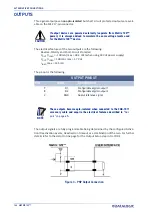
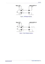
Страница 177: ...OUTPUTS PRODUCT REFERENCE GUIDE 163 Figure 4 NPN Output Connection Figure 5 Push Pull Output Connection ...

Страница 178: ...oltage 18 I1A External Trigger polarity insensitive 19 I1B External Trigger polarity insensitive 6 I2A Input Signal 2 polarity insensitive 10 I2B Input Signal 2 polarity insensitive 8 O1 Configurable Digital Output 1 positive pin 22 O1 Configurable Digital Output 1 negative pin 11 O2 Configurable Digital Output 2 positive pin 12 O2 Configurable Digital Output 2 negative pin 2 TX Transmitted data 3...

Страница 179: ...I O devices These signals are refer enced to GND Orange Input 1 External Trigger Gray Input 2 Input Signal 2 Purple Output 1 Configurable Digital Output 1 Red White Output 2 Configurable Digital Output 2 Black GND Ground Reference Black Thick SHIELD Cable Shield CAB 1051 WIRES PIN NAME DESCRIPTION CAUTION If output devices are powered externally separate from Matrix 120 power it is always advised ...

Страница 180: ...e connector 2 RX 3 RX 3 TX 2 TX 5 GND 7 GND How To Build A Simple Interface Test Cable the following wiring diagram shows a simple test cable including power external push button trigger and PC RS232 COM port connections Figure 7 Test Cable for Matrix 120 RS232 PC SIDE CONNECTIONS Pin Name Pin Name ...

Страница 181: ...symbol consists of a leading margin start character data or message character check character if any stop character and trailing margin Within this framework each recognizable symbology uses its own unique format BIOS Basic Input Output System A collection of ROM based code with a standard API used to interface with standard PC hardware Bit Binary digit One bit is the basic unit of binary informat...

Страница 182: ...used with very reflective surfaces Decode To recognize a barcode symbology e g Codabar Code 128 Code 3 of 9 UPC EAN etc and analyze the content of the barcode scanned Depth of Field The difference between the minimum and the maximum distance of the object in the field of view that appears to be in focus Diffused Illumination Distributed soft lighting from a wide variety of angles used to eliminate...

Страница 183: ...technical Commission Global organization that publishes interna tional standards for electrical electronic and other technologies IP Address The terminal s network address Networks use IP addresses to determine where to send data that is being transmitted over a network An IP address is a 32 bit number referred to as a series of 8 bit numbers in decimal dot notation e g 130 24 34 03 The highest 8 ...

Страница 184: ...ections and stacked one upon another similar to sentences in a paragraph RAM Random Access Memory Data in RAM can be accessed in random order and quickly written and read Symbol Verification The act of processing a code to determine whether or not it meets specific require ments Transmission Control Protocol Internet Protocol TCP IP A suite of standard network protocols that were originally used i...

Страница 185: ......

Страница 186: ......

Страница 187: ......

Страница 188: ...yright no part of this documentation may be repro duced stored in or introduced into a retrieval system or transmitted in any form or by any means or for any purpose without the express written permission of Data logic S p A and or its affiliates Datalogic and the Datalogic logo are registered trademarks of Datalogic S p A in many countries including the U S and the E U www datalogic com 821006441...

Отзывы: