Programming Flowcharts
117
4
4
4
4
4
4
4
4
4
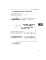
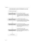
Set the DT3152-LS Specific Controls for the Input Source
Using
Sync Master
mode?
Set the horizontal frequency (fro m 1Hz
to 2 MHz); the vertical frequency (from
1 Hz to 20 0kHz); the width of the
horizontal sync pulses (from 250 ns to
950,000,000 ns; the width of the vertical
sync pulses (from 250 ns to 950,000,000
ns); and the amount the vertical sync is
shifted relative to the horizontal sync
(from 1% (100) to 99% (9900) of the total
line.
Using
area-scan
mode?
No
Yes
Set the Sync Master control values with
Dt3152SetSyncMasterControlValue.
Enable Sync Master mode with
Dt3152EnableSyncMasterMode.
Set the input control values with
Dt3152SetInputControlValue.
Set the gain to 0.5 (50), 1 (100), 2 (200), or 4
(400); the default is 1.
Set the reference from 0 to 1,275,000
µ
V. For
area-scan mode, the default is 700,000
µ
V for 50
Hz and 660,000
µ
V for 60 Hz. For line-scan
mode, the default is 700,000
µ
V.
Set the offset from
−
1,075,200
µ
V to 1,066,800
µ
V. For area-scan mode, the default is 0
µ
V for 50
Hz and
−
53,855
µ
V 60 Hz. For line-scan mode,
the default is 0
µ
V.
No
Yes
Specify the line-sync output with
OlFgSetLsLineDrive.
Specify the integration pulse with
OlFgSetLsIntegration.
Specify the active edge as high-to-low (low is
active) or low-to-high (high is active) and the
number of clock cycles that are counted before
the pulse is active for both the line-sync output
pulse and the integration output pulse.
Specify the master clock divider
with OlFgSetLsDriveClkDiv.
Determines the frequency of the line-sync output
and integration output signals. Divider values
range from 2
0
to 2
12
.
Содержание DT3152-LS
Страница 1: ...MACH Series UM 16481 F DT3152 LS User s Manual ...
Страница 4: ......
Страница 16: ...About this Manual xvi ...
Страница 17: ...1 1 Overview Features 2 Supported Software 4 Accessories 6 ...
Страница 142: ...Chapter 4 126 ...
Страница 143: ...127 5 Troubleshooting General Checklist 128 Service and Support 132 If Your Board Needs Factory Service 136 ...
Страница 153: ...137 A Specifications ...
Страница 156: ...Appendix A 140 ...
Страница 157: ...141 B Connector Pin Assignments Connector J1 Pin Assignments 142 Connector J2 Pin Assignments 144 ...
Страница 162: ...Appendix B 146 ...
Страница 192: ...Appendix C 176 ...
Страница 193: ...177 D Asynchronous Reset Cameras ...
Страница 196: ...Appendix D 180 ...
Страница 210: ......
Страница 214: ......

