Attaching and Configuring a Screw Terminal Panel
37
4
4
4
4
4
4
4
4
4
Configuring a Screw Terminal Panel
This section describes how to locate and configure the jumpers and
resistors on the DT740 or STP268 screw terminal panel for use with a
DT3010 Series board.
Configuring the DT740 Screw Terminal Panel
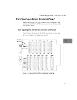
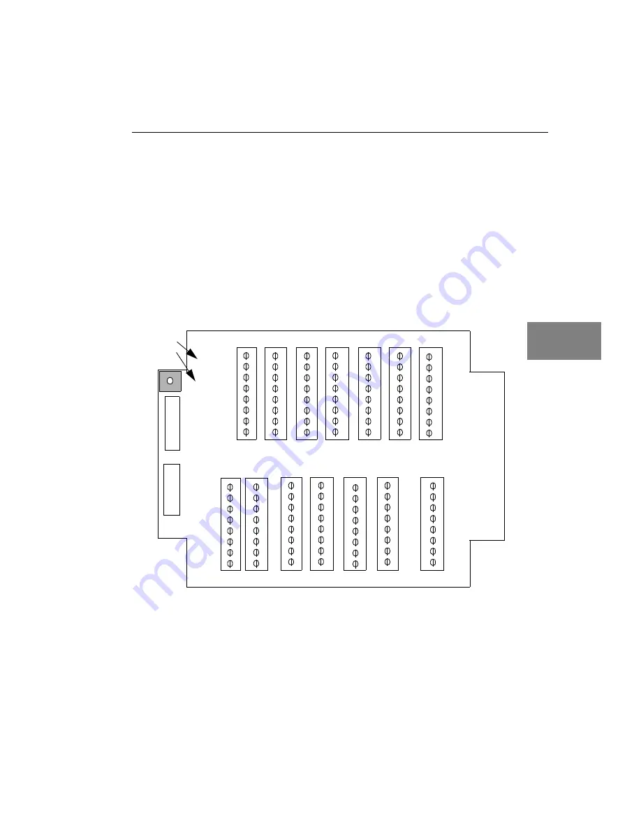
shows the layout of the DT740 screw terminal panel, and
shows the location of the jumper and resistors.
Figure 13: Layout of the DT740 Screw Terminal Panel
J1
J2
1
8
9
16
17
24
32
40
48
56
25
33
41
49
W1
R1 to R16
CTR
57
CTR
65
Trig
73
GND
81
DIO
97
DIO
89
Shield
105
64
72
80
88
96
104
112
Gnd 0
Gate 1
Clk 0
Out 0
Gate 0
Gnd 1
Clk 1
Out 1
R17 to R32
Jumper and
Resistors
Содержание DT3010 Series
Страница 1: ...R DT3010 Series UM 16868 C Getting Started Manual ...
Страница 11: ...1 1 Overview DT3010 Series Key Hardware Features 2 DT3010 Series Software 3 Getting Started Procedure 4 ...
Страница 22: ...Chapter 2 12 ...
Страница 36: ...Chapter 3 26 ...
Страница 114: ...Chapter 5 104 ...
Страница 136: ...Appendix A 126 ...
Страница 142: ...Index 132 ...


