


02-24-15
FALCON 7X
PAGE 4
/ 12
CODDE 1
ISSUE 2
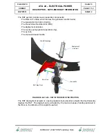
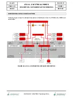
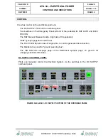
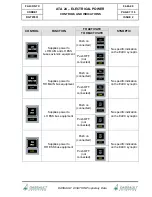
ATA 24 – ELECTRICAL POWER
DESCRIPTION - SUPPLEMENTARY INFORMATION
DGT97831
DASSAULT AVIATION Proprietary Data
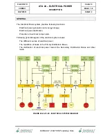
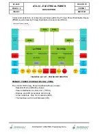
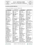
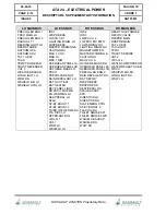
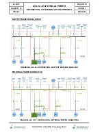
LH MAIN BUS
LH ESS BUS
RH ESS BUS
RH MAIN BUS
PRECOLLER ENG 1
PDCU MAIN LH
PRECOLLER ENG 3
RADIO ALT 1
READING LIGHT LH
REAR STROBE
SATCOM HPA
SATCOM SDU
TAT 1 HEAT
TCAS
TEMP PROBE FAN
TRUST REVERSER
VHF 3
WEATHER RADAR
WING LIGHT LH
WOW RH
WSHIELD B/U LH
WSHIELD CTRL LH
IRS 1
LFSPDB ESS
LGSCU CH 1
LIGHTING MINIM. LH
LRSPDB ESS
MASTER WARNING &
CAUTION RH
MAU 1 CH A
MKB LH
MRC 1 NIM
OVERHEAD PANEL 1A
OVERHEAD PANEL 2B
OXYGENE MASK LH
PDCU
PRECOLLER ENG 1
RAIN REPELLANT LH
RAT GCU TEST
RAT HEATER
REV PANEL LIGHT
RH PDCU B/U PWR
RH WARNING LH
SEAT/PEDAL LH
SFAU
ST-BY BOOST 1
ST-BY BOOST 3
THIRD OXYGEN MASK
TLA DISC LH
UPPER ANTICOL
VIDL-G 1
VHF 1
WOW LH
WSHIELD LH
IRS 2
IRS 3
LGSCU CH 2
LH PDCU B/U PWR
LH WARNING RH
LIGHTING MINIM. RH
MAGNETOMETER
MASTER WARNING &
CAUTION LH
MAU 2 CH A
OXYGENE MASK RH
OVERHEAD PANEL 2A
OVERHEAD PANEL 1B
PRECOLLER ENG 3
RAIN REPELLANT RH
RAT DEPLOY
RFSPDB ESS
RRSPDB ESS
SEAT/PEDAL RH
SFAU BACKUP
SFD
SIDESTICK LH
SIDESTICK RH
SLAT EMERG CTRL
ST-BY BOOST 2
TLA DISC RH
TOILET SMOKE AFT
TOILET SMOKE FWD
WSHIELD BACKUP
WSHIELD RH
WOW RH
REAR TOILET SMOKE
RECIRC VALVE
RFSPDB MAIN
RRSPDB MAIN
TAT 2 HEAT
TAXI LIGHT
TPMU
TOILETS SMOKE
VHF 2
VIDL-G 2
WATER COMPRESSOR
WATER REHEAT HOSE
WSCU
WSHIELD B/U RH
WING LIGHT RH
WOW LH