background image


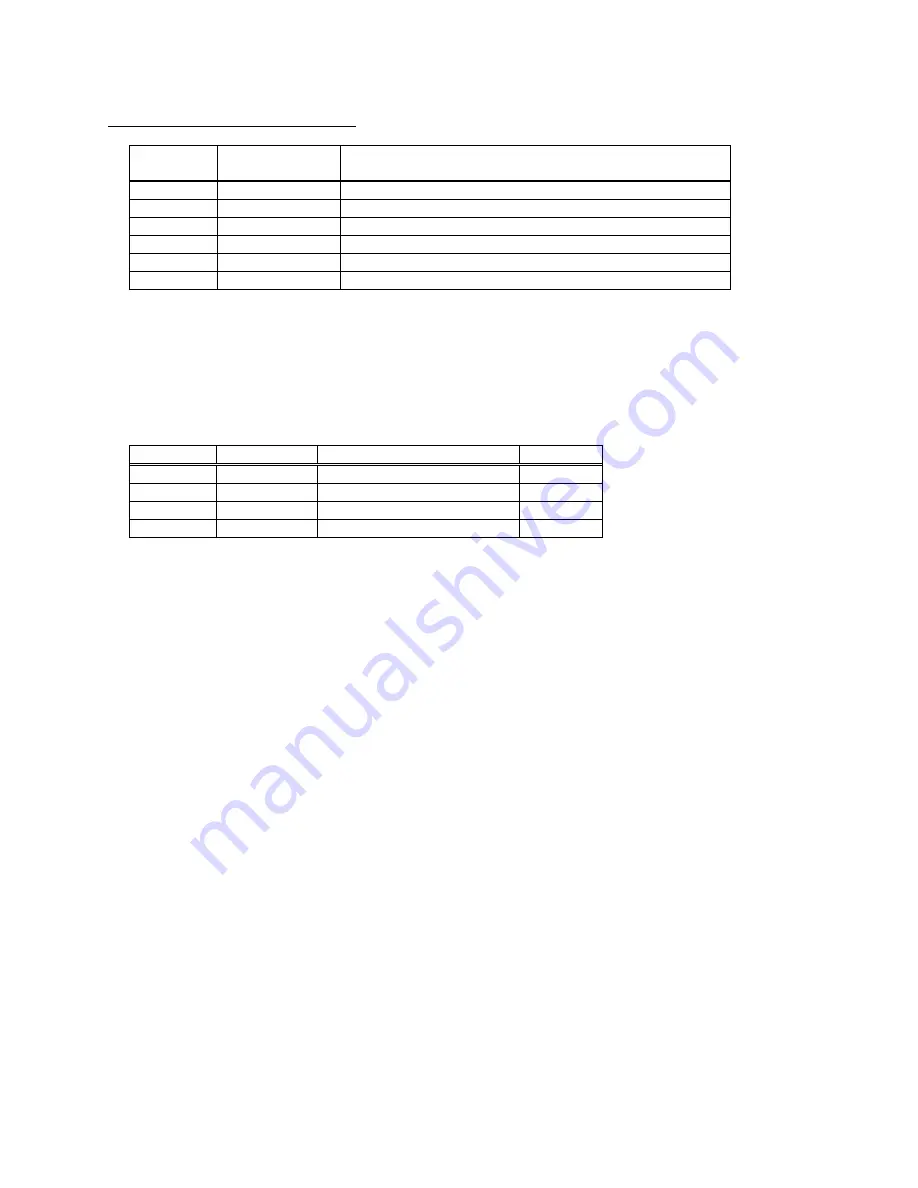
RJ12 Combined Data Socket Detail 
 

Pin 

Signal 

Direction 

Description 

Not Used 

Do Not Connect 

Not Used 

Do Not Connect 

To Printer 

RS-232 Rx data 

To Host 

RS-232 Tx data 

To Host 

RS-232 Busy 

--- 

0V Common (RS-232 signal return and Charger return) 

 
DATA CABLE 
 
An optional serial data cable suitable for connecting the printer to a standard PC is available.  (Note:  This 
cable features an integrated charger connector in the housing of the DB-9 connector which is not required 
for this printer.  Please make no connection to this integrated connector.) 
 
The connections to a standard PC COM port are as follows: 
 

DB-9 Pin 

Name 

Description (refers to PC) 

RJ12 Pin 

3 

TxD 

Serial Data Output 

2 

RxD 

Serial Data Input 

6 & 8 

CTS & DSR 

Busy Input 

SGND 

Signal Common 0V 


EMC STATEMENT  
 
The DT-520 printers are fully EMC (Electro-Magnetic Compatibility) compliant and are CE marked 
accordingly.  A Declaration of Conformity, in accordance with the EMC Directive 89/336/EEC (and as 
amended) is available on request. 
 
EMC Caution 
 
System EMC compliance remains the responsibility of the system designer.  It is recommended that 
shielded cables are used; grounding arrangements will depend on the application.   
 

Содержание DP-520

Страница 1: ...User Guide DP 520 Desktop Printer Dascom Part Number 5206789 Rev A...

Страница 2: ...oling Mode 5 Character Printing and Fonts 5 Graphics Printing and Other Programming Modes 5 Interface Details 6 RS 232 Serial Interface 6 Connections and EMC Precautions 6 Connector Details 6 Connecto...

Страница 3: ...scom reserves the right to modify and improve the firmware in its printer products at any time While every effort is made to ensure backward compatibility no guarantee in this respect is given or impl...

Страница 4: ...ted as soon as complete lines or graphics patterns are decoded It responds to the paper feed button in the normal way and can also produce a self test printout SPOOLING MODE In spooling mode data are...

Страница 5: ...lide the Lid Release Button forwards until the Lid springs open 2 Unwind a small amount of paper from the roll and Insert the Paper Roll into the Printer 3 Close the Lid down and the paper is loaded A...

Страница 6: ...ff Status Indicator Pattern Table Pattern Power Status Buffer Mode Constant Green Running Normal Fast Flashing Green Running Spooling Long Green Short Red Low Voltage Normal Short Green Short Red Low...

Страница 7: ...e host Paper Out condition or Paper Lid open condition being sensed an error condition e g head over temperature power supply over voltage etc In spooling mode the buffered data are stored without bei...

Страница 8: ...es will relax to approximately 0V when the printer is in sleep mode and the user must allow a short period after awakening before relying on the values of these signals Some host equipment use a const...

Страница 9: ...Please make no connection to this integrated connector The connections to a standard PC COM port are as follows DB 9 Pin Name Description refers to PC RJ12 Pin 3 TxD Serial Data Output 3 2 RxD Serial...

Страница 10: ...from the battery cover of the printer as shown below Remove the two break outs using a small screwdriver When attaching to a wall the bracket must be located on the wall using screws and wall plugs as...

Страница 11: ...suitable cable Use either a standard cable from Dascom see Combined Data Charger Adaptor Cable or make up your own using the information in the same section Now you will need to SET UP YOUR COMPUTER...

Страница 12: ...ftware com When using these tools select the Able Systems AP1310 YOUR APPLICATION PROGRAM Once communications between your computer and the printer have been established you can try driving the printe...

Отзывы: