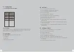
DanVex DEH-10K Скачать руководство пользователя страница 12

6

.

Controller

Terminal

Description

Load

L

-

N

Relay 

1

--

H

Relay 

2

--

M

Relay 

3

--

L

Relay 

4

--

C

Relay 

5

--

NO

Relay 

5

--

NC

EC FAN1

EC FAN2

GND

RS485--AI

RS485--BI

RS485--A2

RS485--BI

12VDC

220VAC

220VAC  output  

Max


1A

220VAC 


o

utput


Max


1A

220VAC 


o

utput


Max


1A

220VAC 


o

utput


Max


1A

220VAC 


o

utput


Max


1A

SPDT(single-pole double-throw)
220VAC  

o

utput  Max   1A

SPDT(single-pole double-throw)

0

--

10V

0

--

10V

Weak current common terminal

Communicate with external temp.& humidity sensor

Communicate with external temp.& humidity sensor

Communicate with third-party

Communicate with third-party

Power the external temp.& humidity sensor

Power supply

High fan speed

Medium fan speed
Fan coil valve

Low fan speed;Humidifier

Compressor

Air damper open

Air damper close

EC motor supply fan

EC motor exhaust fan

12VDC

R

S485-A1

R

S485-

B

1

R

S485-A

2

R

S485-

B2

GND

FAN


1

FAN


2

L

N

H M L

N

O

C

N

C

Neutral

Liv
e

High fan speed

Medium fan speed

Low fan speed

Compr

essor

Air damper open

Air damper close

Temp. & Humidity Sensor

Third party

Third party

EC motor exhaust fan

Common terminal

EC motor exhaust fan

Temp. & Humidity Sensor

12VDC  output

6.1

.

1

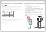
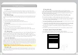
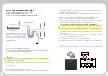
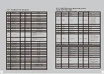
  Controller Terminals:

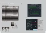
6.1.2  Terminals Diagram:

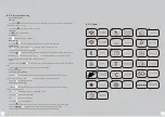
The small number in the top
shows:

The


large


number


shows

:

1.Humidity when the unit is
powered on
2.BLANK when the unit is
pqwered off

Fan speed

Modes

ON

/

OFF

6.1.3   Controller

s Interface:

17

18

6.1  General

1.OFF when the unit is 
pqwered off
2.the error code if there is
alarm
3.the ambient room 
temperture when powered on

Содержание DEH-10K

Страница 1: ...g Dehumidi ers Any questions please contact the manufacturer or dealer in time The repair and maintenance must be conducted by certi fed professionals Please read the manual carefully and in full befo...

Страница 2: ...ates actions that must be prohibited If not strictly followed it may cause serious damage to the machine or personal injury or death When a problem occurs such as a burning smell etc please turn off t...

Страница 3: ...eck 5 2 2 Wiring Check 5 2 3 Controller Check 6 Controller 6 1 General 6 1 1 Controller Terminals 6 1 2 Terminals Diagram 6 1 3 Controller s Interface 6 1 4 Parameters Setting 6 1 5 Icon 6 2 Controlle...

Страница 4: ...peration of the compressor discharge high temperature and high pressure gas from the exhaust port enter the condenser for cooling It becomes a low temperature and high pressure gas intercepted by a ca...

Страница 5: ...e of the equipment can be easily carried out The unique defrosting device effectively guarantees the reliable operation of the dehumidifier The fan adopts a centrifugal external rotor fan steel volute...

Страница 6: ...ane fins the heat exchange efficiency is increased by 20 thus to reduce the unit size and weight The high quality thermal insulation material increases the thermal insulation effect by 15 2 5 5 Thrott...

Страница 7: ...t in humidity temp sensor I IPX3 55DB 60DB 65DB Mitsubishi R410A copper tubes with blue hydrophilic coated aluminum fins SUS304 25 32 32 G4 PRE Filter 1122 600 1850mm DEH 5K DEH 10K 11KW 22KW 20A 40A...

Страница 8: ...led indoors During installation there should be maintenance space at the rear of the dehumidification equipment to facilitate future inspection and maintenance of the equipment For cleaning and mainte...

Страница 9: ...alled at a position 1 meter to 1 5 meters above the ground in order to detect representative water in the controlled area Flat or laid at the inspection point according to the design requirements The...

Страница 10: ...tdoors to extract air as fresh air and then sent to a separate space after dehumidification such as paint spray room purification room 4 1 2 Ducting for Fresh Air Dry air Wet air Wet fresh air Dry fre...

Страница 11: ...idifier unit must be carried out by professional staff Otherwise the company will not be responsible for all the consequences caused Check the installed air filter device to ensure it is in a clean st...

Страница 12: ...um fan speed Fan coil valve Low fan speed Humidifier Compressor Air damper open Air damper close EC motor supply fan EC motor exhaust fan 12VDC RS485 A1 RS485 B1 RS485 A2 RS485 B2 GND FAN 1 FAN 2 L N...

Страница 13: ...umidity press to raise humidity 1 changed each press Long press Short press simultaneously for 5 seconds to display the run time wait for 5 seconds to exit Short press to set the available code Press...

Страница 14: ...es later after achieved the set humidity and temperature only for the available system working mode F01 2 high fan speed low fan speed available High fan speed low fan speed available when H04 1 F01 3...

Страница 15: ...rror code is E01 It will resume operation after the error addressed The error code is E03 It will resume operation after the error addressed if there is RS485 1 communication failure only the fan keep...

Страница 16: ...unction Code Byte Read Only or Read Write Object Read Write 2 bytes 2 bytes 2 bytes 2 bytes 2 bytes 2 bytes 2 bytes 2 bytes 2 bytes 2 bytes 2 bytes 2 bytes 2 bytes 2 bytes 2 bytes 2 bytes Read Write R...

Страница 17: ...e to download Smartlife App 4 Open APP and select Add device 5 Slide to Auto Scan 6 Press and hold on off button for 10 seconds until LCD full display Then release the button 7 APP will discover the d...

Страница 18: ...r it is working normally and callibrate correctly 3 6 months 12 months 8 2 Troubleshooting procedures 8 1 Troubleshooting Introduction The purpose of this chapter is to help the operator of the unit t...

Страница 19: ...C 13 14 t s 9 5 04 8 3 KT1 KT2 04 8 4 H3Y 2 C 360S 9 5 B3 KM3 A1 A2 KT2 360S H3Y 2 C 13 14 t s 9 5 04 9 3 KT2 1 T1 04 3 1 2 T2 04 3 1 3 T3 04 3 1 KM3 KT3 04 9 4 H3Y 2 C 540S 9 5 B4 KM4 A1 A2 KT3 540S...

Отзывы: