background image

12

Operation

Read and understand this Owner's Manual carefully before attempting to operate or adjust
the Danuser G20/40 Digger.  You are responsible for furnishing this manual to others who
may use the unit.  If you have any questions regarding the proper assembly, installation, or
operation of this digger, contact your dealer or Danuser Machine Company, Inc.

STEP 1:

Contact local utility companies to make certain there are no buried gas lines, 
electrical cables, etc. in the work area.  Clear area of objects that could wrap 
around the auger or might be thrown.  Check for ditches, stumps, holes, or other 
obstacles that could cause the tractor to roll.

STEP 2:

Layout and mark where you want to dig your holes.

STEP 3:

Adjust the auger to a vertical position:

a)

Left to right vertical adjustments -
With the PTO disengaged, raise the auger point off the ground.  If the 
auger pitches left or right, turn the adjusting screw or leveling crank on the 
lifting link until the auger appears vertical when looking from the tractor 
seat.  Refer to your tractor operating manual for further instructions on 
three-point hitch adjustments.

b)

Front to back vertical adjustments -
Lower the auger slowly until the point just touches the ground.  Move the 
tractor slowly forward or backward until the auger appears vertical when 
looking from the tractor seat.

STEP 4:

Set the tractor brakes and take the tractor out of gear to hold the tractor on 
location to prevent damage to the digger.

STEP 5:

Slowly lower the auger point to the ground.  Make sure the auger point is on the 
ground before engaging the PTO.

STEP 6:

Lower the auger into the ground slowly, then increase the speed as required so 
the dirt is augured out from the hole.  NEVER exceed 540 RPM.  In many types 
of soil, it may be necessary to hold back against the auger screw suction by 
moving the hydraulic control lever momentarily to either the “HOLD” or 
“RAISE” position to keep the auger from screwing into the ground.

When mounted to the three-point hitch, your digger must be able to raise and
lower through the highest and lowest points of your lift arm travel without
binding against the tractor frame.  If it does bind, adjust the tractor three-point
linkage so that all movement is free.

NOTE

This post hole digger was designed for one-man operation
from the tractor seat.  It is the responsibility of the operator
to see that bystanders and all other people are at least 
twenty-five feet (25') from the digger in operation or under
power.  Serious personal injury or death may result if any
attempt is made to assist digger operation by hand.

D A N G E R

Personal protection equipment including hard hat, safety
glasses, safety shoes, and gloves are recommended during
assembly, installation, operation, adjustment, maintenance,
repair, removal, or movement of the digger.  Do not allow
long hair, loose fitting clothing, or jewelry to be around 
moving parts.

W A R N I N G

Never position the auger
point by hand or with any
tool when the tractor is
running.  Never position
the auger point by putting
your hands on the auger,
gearbox, boom, or 
driveline.

W A R N I N G

Serious injury or death
can result from misuse 
of this equipment.

C A U T I O N

The G20/40 Digger is
designed for 20 to 40
horsepower, Category I
three-point hitch, 540 RPM
PTO tractors using sway
stabilizers.  Auger size
must not exceed 24 inch
diameter.  Operation of
this digger in a manner for
which it was not intended
will result in poor 
performance and could
create a hazard and the
potential for personal
injury.

W A R N I N G

Содержание G20/40

Страница 1: ...ast Third Street P O Box 368 Fulton Missouri 65251 Tel 573 642 2246 Fax 573 642 2240 E mail sales danuser com Website www danuser com Si no entiende ingles se prefiere que busque a alguien que interprete las instrucciones para usted D A N G E R Made in the U S A G20 40 G20 40 9MG20402454105 ...

Страница 2: ...itions is being met with improved manufacturing methods From this sound growth will come new products designed to better serve agriculture and industry Jerry Danuser My grandfather K B Danuser began building wagons and repairing all types of machinery in a small shop in Fulton Missouri in 1910 With pride in his Swiss craftsmanship he established one policy for his concern which is the hallmark of ...

Страница 3: ...fully read each safety message that follows Failure to understand and obey a safety message or recognize a safety hazard could result in injury or death to you or others around you The operator is ultimately responsible for the safety of himself as well as others in the operating area of the post hole digger This is important information for proper use of this equipment Failure to comply may lead ...

Страница 4: ...prior to assembling installing or operating the digger Please remember it is also important that you read understand and follow the safety signs on the digger Clean or replace all safety signs if they cannot be clearly read and understood They are there for your safety as well as the safety of others Danuser Machine Company Inc will furnish new safety signs upon request at no charge All things wit...

Страница 5: ... which can result in serious injury or death Keep hands feet hair jewelry and clothing away from all moving and or rotating parts Never place yourself between the tractor and the digger while the tractor is running To prevent entanglement and possible serious injury or death never use body weight to try to push the auger into the ground Worn edges or a slightly rounded point can seriously affect a...

Страница 6: ...s a primary concern in the design manufacture sale and use of post hole diggers As the manufacturer of your post hole digger we want to confirm to you our customer our concern for safety Our current production post hole diggers include as standard equipment safety signs and shields or guards for auger adapters pinions and drivelines Older machines can be retrofitted to add these safety signs and s...

Страница 7: ...ser Machine Company Inc IMMEDIATELY at 573 642 2246 FIG 1 DANUSER G20 40 DIGGER COMPONENTS Ref Part No Description No Qty 1 Boom 6045 1 2 Pin 3 4 x 8 6056 1 3 Retaining Ring 2172 4 4 Pin 3 4 x 4 15 16 6055 1 5 Pinion Guard 6057 1 6 Driveline 6807 1 7 Yoke 6051 1 8 Roll Pin 3 16 x 1 1 2 6061 1 9 Special Shear Bolt 5 16 18 x 2 1 4 Gr 5 6015 3 one required in unit two spares included 10 Nut 5 16 18 5...

Страница 8: ...hes and auger extensions are available in lengths of 7 and 14 inches Auger diameters range from 4 to 24 inches Auger diameter must not exceed 24 inches Danuser augers are built with special wear resistant steel on the lower flights replaceable cutting edges and replaceable points The auger attaches to the gearbox spindle with a special Grade 8 bolt The shear bolt is a special Grade 5 bolt and conn...

Страница 9: ...low long hair loose fitting clothing or jewelry to be around moving parts W A R N I N G Instructions Refer to Fig 2 STEP 1 Attach the yoke PN 6051 to the boom PN 6045 using pin PN 6055 and retaining rings PN 2172 Stabilize components to avoid pinch points during assembly STEP 2 Attach the boom to the tractor upper link bracket with the tractor upper link pin Avoid pinch points around the pin durin...

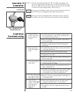
Страница 10: ...f the driveline Grease the grease zerk in the tractor end yoke and in the two center crosses Slide the driveline halves back together with the end yokes in proper alignment see Fig 6 Failure to properly align end yokes may result in excessive vibration Always make sure guards are in place and rotate freely STEP 11 Make sure the tractor engine is shut off then connect the driveline to the tractor P...

Страница 11: ...ch c Relocate or adjust the part of the tractor causing the interference 2 Digger yoke strikes boom when digger is raised a Attach the front end of the boom to a more forward hole on the upper link bracket b Attach the lower links to rear forward pivot points c Lengthen the lower links d Refer to your tractor operating manual for adjustment of the three point hitch 3 Tractor has difficulty raising...

Страница 12: ...red so the dirt is augured out from the hole NEVER exceed 540 RPM In many types of soil it may be necessary to hold back against the auger screw suction by moving the hydraulic control lever momentarily to either the HOLD or RAISE position to keep the auger from screwing into the ground When mounted to the three point hitch your digger must be able to raise and lower through the highest and lowest...

Страница 13: ...of at least twenty five feet 25 around the auger clear of bystanders and all other people D A N G E R Do not shovel dirt away from a rotating auger as the shovel can be caught and thrown by the auger D A N G E R For heavy soil conditions or for tractors requiring driveline rotation to produce lifting power allow the auger to turn at a slow speed while raising it to the top of the hole NOTE This di...

Страница 14: ...ith the tractor PTO engaged C A U T I O N Before digging around the auger disengage the PTO set the tractor brakes shut off the tractor engine and remove the tractor key D A N G E R Keep others at least twenty five feet 25 from the auger when applying lift power to raise the freed auger from the ground Stop auger rotation prior to lifting out of hole D A N G E R Operation continued WHAT TO DO WHEN...

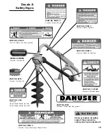
Страница 15: ... PART NO PHDC 5 Location Auger under Auger Adapter Guard PART NO 2088 Locations Boom right side gearbox PART NO 2169 Locations Auger Adapter Shield rear half Auger Adapter Shield front half PART NO 9875 Location Gearbox lid SERIAL NUMBER Location Gearbox lid PART NO 13 10021 Location Driveline Guard W A R N I N G Clean or replace all safety signs if they cannot be clearly read and understood ...

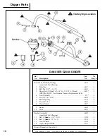
Страница 16: ...t Only 4 Nut 5 16 18 573 3 5 Pin 3 4 x 4 15 16 6055 1 6 Retaining Ring 2172 4 7 Pin 3 4 x 8 6056 1 8 Pinion Guard 6057 1 9 Boom 6045 1 10 Yoke 6051 1 Gearbox Assembly 6042 1 consists of the following 11 Bolt 3 8 16 x 1 1 4 Gr 5 1180 2 12 Bolt 3 8 16 x 7 8 Gr 5 2339 2 13 Nut 3 8 16 2168 4 14 Auger Adapter Shield 6137 2 Owner s Manual in digger box 1 One required in unit Two extra are included in pa...

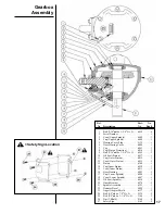
Страница 17: ...0 Oil Seal Pinion 6017 1 11 Cup Outer Pinion 6012 1 12 Cone Outer Pinion 6013 1 13 Pinion 6349 1 14 Cup Inner Pinion 6010 1 15 Cone Inner Pinion 6011 1 16 Gear Housing 6003 1 17 Cup Lower Spindle 6006 1 18 Cone Lower Spindle 6007 1 19 Oil Seal Spindle 6018 1 20 Guard Bracket 6274 1 21 Spindle Assembly 6352 1 22 Danuser Decal 2088 1 23 Auger Adapter Shield 6137 2 24 Bolt 3 8 16 x 7 8 Gr 5 2339 2 25...

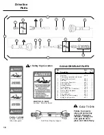
Страница 18: ... 6810 1 9 Tractor Half with Guard 6816 1 10 Outer Guard 6813 1 11 Yoke and Shaft 6812 1 12 Spring Lok Yoke Assembly 7269 1 13 Spring Lok Repair Kit 6131 1 G20 40 DRIVELINE PARTS Safety Sign Location C A U T I O N Failure to properly align end yokes may result in excessive vibration Always be sure guards are in place and rotate freely Part No 13 10022 Location Driveline tube under guard PART NO 13 ...

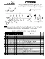
Страница 19: ... 6080G 6080G 6080G 6080G 6080G 6080G 6080G 6080G Auger Extension with Guard 7 1 6204G 6204G 6204G 6204G 6204G 6204G 6204G 6204G Auger Extension with Guard 14 1 11 6239 6239 6239 6239 6239 6239 6239 6239 Coiled Pin 1 2 x 2 3 4 SPECIAL PIN Use Genuine Danuser Replacement Only 1 12 1937 1937 1937 1937 1937 1937 1937 Special Duty Auger Point 1 13 6210 6210 6210 6210 6210 6210 6210 Aggressive Duty Auge...

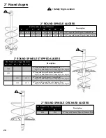
Страница 20: ... of Cutting Edges See Page 19 6249 6250 40 Long with Serrated Edges Standard Point Auger Uses Both Dimensions of Cutting Edges See Page 19 Part Number by Auger Diameter Description 18 24 6256 6255 29 Long with Serrated Edges Standard Point 2 ROUND SPINDLE ORCHARD AUGERS 2 ROUND SPINDLE STEPPED AUGERS Safety Sign Location 20 Part Number by Auger Diameter Description 4 6 9 12 14 16 18 24 6101 6029 6...

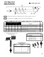
Страница 21: ...56 Retaining Nut 1 2 13 1 4 6019 6019 6019 6019 6019 Auger Adapter Replacement for Field Welding 1 AUGER ASSEMBLIES WITH HOLE DIGGER HEADS FOR 2 ROUND SPINDLES Auger No Teeth Part Diameter per Head No 6 2 9386 9 4 9306 12 4 9308 14 6 9309 16 6 9310 Includes head with teeth and roll pins point and point adapter with tube for welding to auger center column HOLE DIGGER HEAD KIT Field Weld to Auger 3 ...

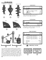
Страница 22: ...EXTENSIONS Ref Part No Description No 1 7 Auger Extension with 2 Special Coiled Pins Auger Extension Guard 6080G 2 14 Auger Extension with 2 Special Coiled Pins Auger Extension Guard 6204G a Safety Sign PHDC5 b Safety Sign 2169 c Decal 6260 d Decal 6262 AUGER POINTS Ref Part No Description No 1 Standard for augers 6 through 24 diameter 831 only point for 4 augers 899 2 Special Duty 1937 3 Aggressi...

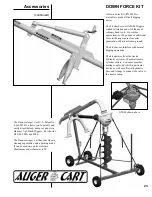
Страница 23: ... the tractor hydraulic system with normal remote cylinder outlets Customer provides mating coupler tip to fit his particular tractor as well as sufficient hydraulic hose and fittings to connect the valve to the tractor sump Accessories continued G20 40 shown above The Danuser Auger Cart U S Patent No 6 419 245 B1 allows you to quickly and easily attach detach transport and store Danuser 3 pt Hitch...

Страница 24: ...This page is intentionally blank ...

Страница 25: ...nts arriving at our factory on a freight collect basis will be refused by our receiving department 5 All parts returned under a warranty inspection claim must be returned PREPAID to our factory The freight charge will be credited if the parts are determined by Danuser Machine Company Inc to be defective 6 Products or parts thereof which as determined by Danuser Machine Company Inc s examination sh...

Страница 26: ...mportant safety rules to be understood and followed by anyone who works with post hole diggers Before operating a post hole digger an operator must read and understand all the information in the owner s manual and in the safety signs attached to the product A person who has not read or understood the owner s manual and safety signs is not qualified to operate the digger If you do not have an owner...

Отзывы: