background image

_______________________________________________________________________________________ 

_______________________________________________________________________________________ 

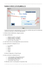
“STATUS” PAGE [MENU no.3] 


Typically, the user only accesses this page in the event of an error, in which case the cooler icon is red. The 
information available is: 


1)  Modbus Address of the cooler connected to the panel; 


2)  Status of the cooler: 


Offline - (black icon);  


Standby - (yellow icon); 


Running - (green icon); 


Fault - (red icon). 


3)  Fault Code accompanied by a short description;


4)  Drop-down menu for configuration as:


Not installed; 


Zone 1; 


Zone 2; 


Zone 3; 


Zone 4;


Single.


The default configuration is "Single". 
 

5)  Drop-down menu for configuration as:


"Local Temperature" (Single or Zone Master); 


"Local Humidity" (Single or Zone Master); 


"Area Temperature" (Zone Slave); 


"Areal Humidity" (Zone Slave). 

 
The default must be “Local Temperature”. 


Содержание MASTER SM 4.0

Страница 1: ...______________________________________________________________ _______________________________________________________________________________________ SM 4 0 DISPLAY 4 USER AND MAINTENANCE BOOK en INS...

Страница 2: ...o 1 The hmi once powered and connected to the cooler presents the screen in Pic 1 with the following information 1 Temperature measured by the ntc probe of the cooler 2 Target temperature by touching...

Страница 3: ...ack icon Standby yellow icon Running green icon Fault red icon In the event of a Fault clicking on the icon takes you to a page that provides the error code and a brief description of the error 9 Cool...

Страница 4: ...a machine in which case the modbus address of the cooler to be controlled must be set 2 The Clock i e date and time operationally you have to position yourself on the parameter you want to set and act...

Страница 5: ...s 1 Modbus Address of the cooler connected to the panel 2 Status of the cooler Offline black icon Standby yellow icon Running green icon Fault red icon 3 Fault Code accompanied by a short description...

Страница 6: ...e at which it is activated and the function associated with it Each time slot once created can also be modified at a later date by clicking on icon no 2 in Pic 4 To delete a time slot click on icon No...

Страница 7: ...Resistive CPU ARM Cortex A8 1 GHz Operating System Linux 3 12 Flash 4 GB RAM 512 MB Real Time Clock RTC Back up Buzzer Yes Interface Ethernet port 1 port 0 10 100 USB port 1 Host v 2 0 max 500 mA Seri...

Страница 8: ...owed to comply with front panel protection ratings The edges of the cutout must be flat Tighten each fixing screw until the corner of the plastic faceplate comes into contact with the panel The cutout...

Страница 9: ...________________________________________________________________________________ INSTALLATION PROCEDURE Pic 6 Position the fixing brackets contained in the fixing kit as shown in Pic 6 Tightening torq...

Страница 10: ...________________________ _______________________________________________________________________________________ CONNECTIONS 1 Serial Port 2 Ethernet Port 3 USB Port 4 Power Supply To operate with a 2...

Страница 11: ...helps to limit the effects of noise due to electromagnetic interference on the control system Also earth terminal 3 on the power supply terminal block The power supply circuit may be floating or earth...

Страница 12: ..._______________________________________________________________________________________ _______________________________________________________________________________________ 4250 294 Edition 21 Vers...

Страница 13: ...___________________________________________________________________________ _______________________________________________________________________________________ SM 4 0 DISPLAY 4 LIBRETTO USO E MANU...

Страница 14: ...o e collegato al raffrescatore presenta la schermata di Fig 1 con le seguenti informazioni 1 Temperatura misurata dalla sonda ntc del raffrescatore 2 Target temperatura toccando il riquadro appare una...

Страница 15: ...rore icona rossa In caso di Fault raffrescatore in errore cliccando sull icona si accede ad una pagina che fornisce il codice errore e una breve descrizione dello stesso 9 Pulsante on off del raffresc...

Страница 16: ...re il funzionamento di una macchina in questo caso occorre impostare il modbus address del raffrescatore che si vuole pilotare 2 Il Clock ovvero data e ora operativamente occorre posizionarsi sul para...

Страница 17: ...ato al pannello 2 Status del raffrescatore Offline Fuori servizio icona nera Standby In attesa icona gialla Running In funzione icona verde Fault In errore icona rossa 3 Fault Code Codice errore accom...

Страница 18: ...cui si attiva e la funzione ad essa associata Ogni fascia oraria una volta creata pu essere modificata anche successivamente agendo sull icona n 2 in Fig 4 Per eliminare una fascia oraria agire sull...

Страница 19: ...esistive CPU ARM Cortex A8 1 GHz Operating System Linux 3 12 Flash 4 GB RAM 512 MB Real Time Clock RTC Back up Buzzer Yes Interface Ethernet port 1 port 0 10 100 USB port 1 Host v 2 0 max 500 mA Seria...

Страница 20: ...bordi del ritaglio devono essere piatti Avvitare ciascuna vite di fissaggio fino a quando l angolo del frontalino in plastica non viene a contatto con il pannello Il ritaglio per il pannello deve esse...

Страница 21: ...__________________________________________________________ PROCEDURA DI INSTALLAZIONE Fig 6 Posizionare le staffe di fissaggio contenute nel kit di fissaggio come mostrato in Fig 6 Coppia di serraggio...

Страница 22: ..._________________ _______________________________________________________________________________________ CONNESSIONI 1 Serial Port 2 Ethernet Port 3 USB Port 4 Power Supply Per operare con un modbus...

Страница 23: ...uto all interferenza elettromagnetica sul sistema di controllo Collegare anche a terra il terminale 3 sulla morsettiera dell alimentatore Il circuito di alimentazione potrebbe essere flottante o messo...

Страница 24: ..._______________________________________________________________________________________ _______________________________________________________________________________________ 4250 294 Edition 21 Vers...

Страница 25: ..._________________________________________________________________________ _______________________________________________________________________________________ SM 4 0 DISPLAY 4 BEDIENUNGS UND WARTUN...

Страница 26: ...g und dem K hlger t wird der Bildschirm von ABB 1 mit den folgenden Informationen angezeigt 1 Von dem ntc F hler des K hlger ts gemessene Temperatur 2 Target Temperatur durch Ber hrung des Felds ersch...

Страница 27: ...ymbol Fault Fehlerhaft rotes Symbol Im Falle eines Faults K hlger t in Fehler wird durch Anklicken des Symbols eine Seite aufgerufen die den Fehlercode und eine kurze Beschreibung des Fehlers angibt 9...

Страница 28: ...Betrieb einer Maschine zu berpr fen In diesem Fall ist es erforderlich die Modbus Adresse des K hlger ts einzustellen das angesteuert werden soll 2 Clock d h Datum und Uhrzeit zur Einstellung sich auf...

Страница 29: ...tatus des K hlger ts Offline Kein Dienst schwarzes Symbol Standby Warten gelbes Symbol Running In Betrieb gr nes Symbol Fault Fehlerhaft rotes Symbol 3 Fault Code Fehlercode mit einer kurzen Beschreib...

Страница 30: ...ktiviert wird und die damit verbundene Funktion an Jedes einmal erstellte Zeitfenster kann auch nachtr glich ber das Symbol Nr 2 in ABB 4 ge ndert werden Zur L schung eines Zeitfensters das Symbol Nr...

Страница 31: ...Resistive CPU ARM Cortex A8 1 GHz Operating System Linux 3 12 Flash 4 GB RAM 512 MB Real Time Clock RTC Back up Buzzer Yes Interface Ethernet port 1 port 0 10 100 USB port 1 Host v 2 0 max 500 mA Seri...

Страница 32: ...verlaufen Jede Befestigungsschraube so festziehen dass die Ecke der Kunststoffblende Kontakt mit der Bedientafel hat Die Aussparung f r die Bedientafel muss die in diesem Handbuch angegebenen Abmessu...

Страница 33: ...______________________________________________________________________ INSTALLATIONSVERFAHREN ABB 6 Die im Befestigungsset enthaltenen Befestigungsb gel wie in ABB 6 dargestellt anbringen Anzugsmoment...

Страница 34: ...________ _______________________________________________________________________________________ ANSCHL SSE 1 Serial Port 2 Ethernet Port 3 USB Port 4 Power Supply F r den Betrieb mit einem Modbus RS4...

Страница 35: ...lektromagnetische Interferenzen auf das Steuersystem zu begrenzen Auch die Klemme 3 am Klemmenblock des Netzteils erden Der Stromkreis kann potentialfrei oder geerdet sein Im letzteren Fall die gemein...

Страница 36: ..._______________________________________________________________________________________ _______________________________________________________________________________________ 4250 294 Edition 21 Vers...

Страница 37: ...__________________________________________________________________________ _______________________________________________________________________________________ SM 4 0 DISPLAY 4 FOLLETO DE USO Y MAN...

Страница 38: ...alimentado y conectado al refrigerador presenta la pantalla de la Fig 1 con la siguiente informaci n 1 Temperatura medida por la sonda ntc del acondicionador 2 Temperatura objetivo tocando la casilla...

Страница 39: ...lo En error icono rojo En caso de Fallo pulsando sobre el icono se accede a una p gina que proporciona el c digo de error y una breve descripci n del mismo 9 Bot n de encendido apagado del acondiciona...

Страница 40: ...funcionamiento de una m quina en este caso es necesario establecer la direcci n modbus del acondicionador que se desea manejar 2 El Reloj o fecha y hora operativamente debe posicionarse sobre el par...

Страница 41: ...l 2 Status de la nevera Offline Fuera de l nea icono negro Standby En espera icono amarillo Running En marcha icono verde Fallo En error icono rojo 3 Fault Code C digo de aver a acompa ado de una brev...

Страница 42: ...unci n asociada a ella Cada franja horaria una vez creada puede modificarse tambi n posteriormente actuando sobre el icono n 2 de la Fig 4 Para eliminar una franja horaria act e sobre el icono n 3 de...

Страница 43: ...ARM Cortex A8 1 GHz Sistema operativo Linux 3 12 Flash 4 GB RAM 512 MB Reloj en tiempo real Back up RTC zumbador Yes S Interfaz puerto Ethernet 1 puerto 0 10 100 Puerto USB 1 Host v 2 0 m x 500 mA Pue...

Страница 44: ...procedimiento de instalaci n adecuado Los bordes del recorte deben ser planos Apriete cada tornillo de fijaci n hasta que la esquina de la placa frontal de pl stico haga contacto con el panel El reco...

Страница 45: ...________________________________________________________________ PROCEDIMIENTO DE INSTALACI N Fig 6 Coloque los soportes de fijaci n contenidos en el kit de fijaci n como se muestra en la Fig 6 Par de...

Страница 46: ..._____________ _______________________________________________________________________________________ CONEXIONES 1 Puerto de serie 2 Puerto Ethernet 3 Puerto USB 4 Alimentaci n Para operar con un modb...

Страница 47: ...cias electromagn ticas en el sistema de control Conecte tambi n a tierra el terminal 3 del bloque de terminales de la fuente de alimentaci n El circuito de alimentaci n puede ser flotante o estar cone...

Страница 48: ..._______________________________________________________________________________________ _______________________________________________________________________________________ 4250 294 Edici n 21 Vers...

Страница 49: ...______________________________________________________________________ _______________________________________________________________________________________ SM 4 0 DISPLAY 4 NOTICE D UTILISATION ET...

Страница 50: ...isseur l IHM pr sente la page cran de la Fig 1 avec les informations suivantes 1 Temp rature mesur e par la sonde ntc du rafra chisseur 2 Target temp rature en touchant l encadr s affiche un clavier p...

Страница 51: ...ult en erreur ic ne rouge En cas de Faut rafra chisseur en erreur cliquer sur l ic ne permet d acc der une page qui fournit le code d erreur et une description rapide 9 Bouton ON OFF du rafra chisseur...

Страница 52: ...ent d une machine dans ce cas il est n cessaire de configurer le modbus address du rafra chisseur piloter 2 L horloge c est dire la date et l heure il faut se placer op rationnellement sur le param tr...

Страница 53: ...nneau 2 tat du rafra chisseur Offline hors service ic ne noire Standby en attente ic ne jaune Running en service ic ne verte Fault en erreur ic ne rouge 3 Fault Code Code d erreur accompagn d une desc...

Страница 54: ...quel elle s active et la fonction associ e Une fois cr e chaque plage horaire peut tre modifi e aussi par la suite en agissant sur l ic ne n 2 de la Fig 4 Pour liminer une plage horaire agir sur l ic...

Страница 55: ...n Resistive CPU ARM Cortex A8 1 GHz Operating System Linux 3 12 Flash 4 GB RAM 512 MB Real Time Clock RTC Back up Buzzer Yes Interface Ethernet port 1 port 0 10 100 USB port 1 Host v 2 0 max 500 mA Se...

Страница 56: ...bords de la d coupe doivent tre plats Visser chaque vis de fixation jusqu ce que l angle de la fa ade en plastique entre en contact avec le panneau La d coupe pour le panneau doit respecter les dimens...

Страница 57: ...____________________________________________________________________ PROC DURE D INSTALLATION Fig 6 Placer les triers de fixation contenus dans le kit de fixation comme illustr sur la Fig 6 Couple de...

Страница 58: ...________________ _______________________________________________________________________________________ CONNEXIONS 1 Serial Port 2 Ethernet Port 3 USB Port 4 Power Supply Pour fonctionner avec un mod...

Страница 59: ...lectromagn tique sur le syst me de contr le Brancher aussi la terre la borne 3 sur le bornier du bloc d alimentation Le circuit d alimentation pourrait tre flottant ou mis la terre Dans ce cas branche...

Страница 60: ..._______________________________________________________________________________________ _______________________________________________________________________________________ 4250 294 Edition 21 Vers...

Страница 61: ..._________________________________________________________________________ _______________________________________________________________________________________ SM 4 0 DISPLAY 4 INSTRUKCJA OBS UGI I...

Страница 62: ...niu i pod czeniu do ch odziarki hmi prezentuje ekran z RYS 1 z nast puj cymi informacjami 1 Temperatura mierzona przez sond ntc klimatyzatora 2 Temperatura docelowa po dotkni ciu pola pojawia si klawi...

Страница 63: ...Praca ikona zielona Fault B d ikona czerwona W przypadku B du b d klimatyzatora klikaj c na ikon uzyskuje si dost p do strony kt ra podaje kod b du i kr tki opis b du 9 Przycisk on off klimatyzatora...

Страница 64: ...ryfikacji pracy maszyny w tym przypadku konieczne jest ustawienie adresu Mobus klimatyzatora kt r chcemy sterowa 2 Zegar lub data i czas operacyjnie musisz ustawi si na parametrze kt ry chcesz ustawi...

Страница 65: ...imatyzatora Offline Nie dzia a ikona czarna Standby W oczekiwaniu ta ikona Running Praca ikona zielona Fault B d ikona czerwona 3 Kod usterki wraz z kr tkim opisem 4 Menu rozwijane do konfiguracji jak...

Страница 66: ...t aktywny oraz funkcj z nim zwi zan Ka dy raz utworzony przedzia czasowy mo na r wnie p niej modyfikowa poprzez dzia anie na ikon nr 2 na RYS 4 Aby usun przedzia czasowy nale y klikn na ikon nr 3 na R...

Страница 67: ...k Ekran dotykowy Resistive Rezystancyjny CPU ARM Cortex A8 1 GHz Operating System Linux 3 12 Flash 4 GB RAM 512 MB Zegar czasu rzeczywistego podtrzymanie RTC brz czyk Yes Tak Interfejs Ethernet port 1...

Страница 68: ...rzestrzega odpowiedniej procedury instalacji Kraw dzie wyci cia powinny by p askie Dokr ka d rub mocuj c a r g plastikowej p yty czo owej zetknie si z panelem Wyci cie na panel musi mie rozmiar podany...

Страница 69: ...____ _______________________________________________________________________________________ PROCEDURA INSTALACJI RYS 6 Ustawi uchwyty mocuj ce zawarte w zestawie mocuj cym w spos b pokazany na RYS 6...

Страница 70: ..._______________________ _______________________________________________________________________________________ PO CZENIA 1 Port szeregowy 2 Ethernet Port 3 Port USB 4 Power Supply Aby pracowa z 2 prz...

Страница 71: ...a ograniczy wp yw zak ce elektromagnetycznych na uk ad sterowania Uziemi r wnie zacisk 3 na bloku zacisk w zasilacza Obw d zasilania mo e by p ywaj cy lub uziemiony W tym ostatnim przypadku nale y uzi...

Страница 72: ..._______________________________________________________________________________________ _______________________________________________________________________________________ 4250 294 Wydanie 21 Wer...

Страница 73: ..._______________________________________________________________________________________ _______________________________________________________________________________________ SM 4 0 4 ru...

Страница 74: ...__________________________________________________________________________________ _______________________________________________________________________________________ 1 1 1 ntc 2 3 Timer Clean Pul...

Страница 75: ...__________________________________ _______________________________________________________________________________________ 4 5 6 7 8 Offline Standby Running Fault 9 10 Cooling Ventilation Exhaust Clea...

Страница 76: ..._______________________________________________________ _______________________________________________________________________________________ SETTINGS 2 Main Settings 1 Modbus 1 modbus 2 RTC 3 1 48...

Страница 77: ..._________________ _______________________________________________________________________________________ STATUS 3 1 Modbus 2 Offline Standby Running Fault 3 Fault Code 4 1 2 3 4 Single 5 Local Temper...

Страница 78: ...___________________________________________________________________ _______________________________________________________________________________________ TIMER 4 Timer 1 4 n 2 4 n 3 4 5 4 5 6 7 ON O...

Страница 79: ...___________________ _______________________________________________________________________________________ 4 3 TFT 16 9 64K 480 272 200 2 ARM Cortex A8 1 Linux 3 12 Flash 4 GB 512 MB RTC Ethernet 1 0...

Страница 80: ..._____ _______________________________________________________________________________________ 0 50 C 20 C 70 C 5 85 IP66 2 4X IP20 x 147 107 5 78 4 21 AxB 29 5 1 14 0 19 D T 29 5 1 14 0 19 0 4 CE EN 6...

Страница 81: ..._______________________________________________________________________________________ _______________________________________________________________________________________ 6 6 75...

Страница 82: ...______________________________________________________________________________ _______________________________________________________________________________________ 1 2 Ethernet 3 USB 4 RS485 modbus...

Страница 83: ..._______________________________________________________________________________________ _______________________________________________________________________________________ ETHERNET 1 5 3 1 M 4 7...

Страница 84: ..._______________________________________________________________________________________ _______________________________________________________________________________________ 4250 294 21...

Отзывы: