background image


106 

Guida alla manutenzione 


Introduzione 

Il deumidificatore richiede una manutenzione veramente minima per garantirne un 
funzionamento privo di problemi. Infatti tutte le funzioni di sicurezza e di controllo sono 
già inserite nell’unità. Il motore del/i ventilatore/i e il compressore hanno un sistema di 
lubrificazione permanente e non richiedono una manutenzione particolare. 


Manutenzione 
mensile 

Una volta al mese il filtro d’aspirazione dovrebbe essere controllato e, se necessario, 
pulito. Vaschetta e fognature devono essere puliti di sporco così l'acqua può 
liberamente fuga. 

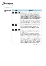
Attenersi alla seguente procedura per eseguire la manutenzione mensile: 


Passo 

Azione 

Per eseguire questa operazione bisogna aprire la portina d’ispezione 

Estrarre il porta filtro, e rimuovere il filtro 

Il filtro dovrà essere pulito con acqua tiepida e sapone oppure, nel caso in cui il 
filtro sia leggermente sporco, può essere utilizzato un semplice aspiratore 

Una volta terminata la pulizia, rimettere il filtro nel porta filtro e riporlo 
all’interno dell’unità 


Manutenzione 
annuale 

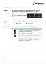
Una volta all’anno l’interno dell’unità dovrebbe essere controllato e pulito. Attenersi alla 
seguente procedura per eseguire la manutenzione annuale: 


Passo 

Azione 

Questa operazione può essere fatta aprendo la portina d’ispezione e 
rimuovendo il pannello frontale 

Se l’unità è sporca, può essere pulita con un aspiratore. Specialmente il 
condensatore ed il rotore del ventilatore dovrebbero essere accuratamente 
puliti utilizzando un aspiratore 

Se le lamelle dell’evaporatore sono molto sporche potranno essere lavate 
con acqua tiepida e sapone 


Revisione 
componenti 

In molti casi i componenti dell’unità possono essere revisionati rimuovendo la portina 
d’ispezione e i pannelli di copertura. Negli altri casi si può estrarre l’intera struttura sulla 
quale sono montati tutti i componenti utilizzando le seguenti istruzioni.  

NOTA! La revisione dell’apparecchio dovrà essere effettuata solamente da un tecnico 
specializzato. 

Attenersi alla seguente procedura per eseguire il revisione componenti: 


Passo 

Azione 

Spegnere l’apparecchio dall’interruttore principale 

Aprire la portina d’ispezione e rimuovere il pannello frontale 

Rimuovere la sezione centrale con il pannello di controllo 

Svitare le viti lungo la struttura di supporto 

Togliere la struttura di supporto. Se la si deve estrarre completamente è 
necessario disconnettere anche i cavi del ventilatore. 


Содержание cdp 75

Страница 1: ...165 Service manual DA EN DE FR RU FR IT No 975672 Rev 3 3 28 10 2010 DA Luftaffugter Side 6 EN Dehumidifier Page 23 Luftentfeuchter Seite 40 DE D shumidificateur Pages 57 FR 74 RU DA IT Deumidificator...

Страница 2: ...hold for trykfejl og ndringer Dantherm can accept no responsibility for possible errors and changes Irrt mer und nderungen vorbehalten Dantherm n assume aucune responsabilit pour erreurs et modificati...

Страница 3: ...l description 25 Display 27 Hygrostat and other control options 13 Mounting and installation instructions 32 Service guide 36 Fault finding guide 37 Technical information 38 EN Service agreement 39 In...

Страница 4: ...iques techniques 72 FR Contrat de service apr s vente 73 74 75 77 79 o 13 84 89 90 91 92 Introduzione 93 Informazioni generali 94 Descrizione prodotto e relative funzioni 95 Display 97 Igrostato e ult...

Страница 5: ...hltem Verfl ssiger CDP 125 165 avec condenseur eau CDP 125 165 CDP 125 165 con consendatore raffreddato ad acqua 119 Eldiagram Wiring diagram Schaltplan Sch ma lectrique Schema elettrico CDP 75 121 E...

Страница 6: ...t kende den korrekte driftsprocedure for aggregatet og alle sikkerhedsforanstaltningerne for at und g mulig skade p materiel og eller mandskab Indhold Denne servicemanual d kker f lgende emner Emne Se...

Страница 7: ...overensstem melseserkl ring Dantherm Air Handling A S Marienlystvej 65 DK 7800 Skive erkl rer p eget ansvar at f lgende produkt Luftaffugter type CDP 75 125 165 som er omfattet af denne erkl ring er i...

Страница 8: ...af den varme der frigives ved vanddampenes kondensering samt varmetil skuddet der stammer fra kompressorens driftseffekt tilf res luften mere varme end der blev fjernet fra den under afk lingen Dette...

Страница 9: ...en ved klemme 7 og 8 Kompressor Start af kompressoren er begr nset af en timer p 6 minutter der starter n r kom pressoren tilsluttes Afbrydes kompressoren skal timeren v re udl bet f r kompres soren k...

Страница 10: ...tydning Nedenst ende giver et overblik over lysdiodernes betydning Hvis affugteren afbrydes og genindkobles via hovedafbryderen vil de fire verste lys dioder p skift lyse gr nt inden affugterens drift...

Страница 11: ...er men der har v ret en fejl p affugteren via lavtrykspressostaten Den blinkende dr be slukkes ved at afbryde og starte affug teren p hovedafbryderen Lynet lyser konstant gr nt for at indikere at str...

Страница 12: ...e skal trykknappen v re placeret i hen holdsvis position A eller B Trykknappernes funktion Nedenst ende giver et overblik over trykknappernes funktion Trykknap Beskrivelse P trykknappen med dr besymbo...

Страница 13: ...til hygrostaten er 12 V Trin Handling 1 Hygrostaten monteres i klemme 3 og 4 efter fjernelse af lusen Rumtermostat Styringen er forberedt for tilkobling af en rumtermostat til placering i det rum der...

Страница 14: ...toren leder rumluften over fordamperfladen indtil afrimningsf leren igen registrerer en temperatur over 5 C Denne afrimningsprocedure betegnes som passiv behovsstyret afrimning idet afrim ningen kun f...

Страница 15: ...g anbefales det at monte re svingningsd mpere mellem affugteren og v goph nget V goph nget leveres som tilbeh r efter nske Vigtigt Ved placering af affugteren skal der v re fri adgang til affugterens...

Страница 16: ...ugterens inspektionsside kan flyttes til den modsatte side hvilket g res p f lgende m de Trin Handling 1 D kpladen p affugterens bagside afmonteres 2 Inspektionsl gen og d kpladen p affugterens forsid...

Страница 17: ...eren Vandvarmefladen er beregnet til montering i udbl sningskanalen Fladen er forsynet med kanaltilslutningsstudse s ledes at den kan forbindes direkte til affugterens tilslut ningsstuds Tekniske data...

Страница 18: ...ner skal overholdes Vandkvalitet Anvisninger fra leverand ren af vandbehandlingsanl gget skal altid overholdes Med tils tning af kemikalier Flg vejledende gr nsev rdier er g ldende for sv mmebassiner...

Страница 19: ...ang rligt efterses indvendigt for snavs F lg denne vejledning for at udf re den rlige servicering Trin Handling 1 Inspektionsl gen bnes og d kpladen front fjernes 2 St vsug affugteren s st v og snavs...

Страница 20: ...gne genindkob linger af h jtrykspressostaten og termorel et b r f lgende kontrolleres Kontroller om rumtemperaturen er mellem 20 og 38 C Kontroller om ventilatoren k rer Kontroller om ind udbl sningsk...

Страница 21: ...aksimum modtryk Pa 140 230 240 Nettilslutning V Hz 1 230 50 1 230 50 3 x 400 50 3 230 50 3 x 400 50 Maksimum effektoptagelse kW 1 85 3 2 4 3 Maksimum ampereforbrug A 9 5 14 0 7 6 20 2 11 5 K lemiddel...

Страница 22: ...eholdelse Dantherm Air Handling A S tilbyder at udf re forebyggende vedligeholdelse p aggre gater s ledes at de til hver en tid k rer tilfredsstillende Reparation og ud kald I tilf lde af funktionsfej...

Страница 23: ...important to know the correct operating procedures for the unit and all safety precautions to prevent the pos sibility of property damage and or personal injury Contents This service manual covers th...

Страница 24: ...ling A S Marienlystvej 65 DK 7800 Skive hereby declare that the units mentioned below Dehumidifiers type CDP 75 125 165 are in conformity with the following directives 98 37 EEC Directive on the safet...

Страница 25: ...cold air is then passed through the condenser where it is reheated As a result of the released evaporator heat and the working energy of the compressor being turned into heat energy more heat is retu...

Страница 26: ...tween terminals 7 and 8 has to be removed first Compressor The number of compressor startings is limited by a 6 minutes timer which starts up when switching on the compressor The timer must have come...

Страница 27: ...ning of the LEDs The table gives an overview of the meaning of the LEDs If the unit is switched off and restarted by connecting and disconnecting power the LEDs will light up green in turn before the...

Страница 28: ...a failure on the unit through the LP pressostat The flashing Drop is switched off by turning the unit OFF and ON on the main switch A constantly green Lightning indicates that power is on The Drop an...

Страница 29: ...uttons should be as follows Functions of the push button The table gives an overview of the push button functions Push button Description By means of the push button with a Drop symbol dehumidifica ti...

Страница 30: ...on 1 The hygrostat is connected to the terminals 3 and 4 after having taken away the bridge Room thermostat The control is prepared for connection of a room thermostat which is placed in the room to b...

Страница 31: ...fan leads the room air over the evaporator coil until the defrosting sensor registers that the temperature has reached 5 C This defrosting process is called passive demands related defrosting as it o...

Страница 32: ...recommend oscillation dampers to be fitted between the unit and the suspension brackets The suspension brackets are available as options on request Important When placing the dehumidifier unimpeded a...

Страница 33: ...l panel Changing the inspection side The inspection side of the unit can be changed to the opposite side It is done as fol lows Step Action 1 Remove the rear cover panel 2 Remove the inspection door a...

Страница 34: ...on spigots allowing direct fixing to the connections of the units The technical specifications for the water heating coils are given in the table on page 110 Connection of water heating coils The cont...

Страница 35: ...ical connections must be made in accordance with local power supply com pany regulations With addition of chemicals The following guidance values are applicable to swimming pools with the addition of...

Страница 36: ...w this procedure to perform the annual service Step Action 1 Open the inspection door and remove the front cover panel 2 If the unit is dirty it may be cleaned with a vacuum cleaner Important Especial...

Страница 37: ...oes not work after several reset tings of HP pressostat and thermal relay Check that the room temperature is between 20 and 38 C Check that the fan is running Check that the inlet and outlet air duct...

Страница 38: ...sure Pa 140 230 240 Power supply V Hz 1 230 50 1 230 50 3 x 400 50 3 230 50 3 x 400 50 Max power consumption kW 1 85 3 2 4 3 Max ampere consumption A 9 5 14 0 7 6 20 2 11 5 Refrigerant R407C R407C R40...

Страница 39: ...maintenance Dantherm Air Handling A S offers to do the preventive maintenance on the units so that they at all times will operate according to factory standards Corrective and emergency repair In case...

Страница 40: ...orrekten Betriebsverfahren und den Sicherheitsmassnahmen bekannt zu machen damit Material und oder Personal keinen Schaden erleiden Inhalt Diese Serviceanleitung behandelt die untenstehenden Themen Th...

Страница 41: ...hs durchzuf hren EG Konformi t tserkl rung Dantherm Air Handling A S Marienlystvej 65 DK 7800 Skive erkl rt auf eigene Ver antwortung dass folgende Ger te Luftentfeuchter Typ CDP 75 125 165 welche von...

Страница 42: ...freiwerdenden Kondensationsw rme und der in W rme umgewandelten An triebsenergie des Kompressors wird der Luft mehr W rme zugef hrt als ihr vorher ent zogen worden ist Diese W rmezufuhr entspricht ung...

Страница 43: ...be tr gt 12 V Die Br cke zwischen den Klemmen 7 und 8 muss vor dem Anschluss ent fernt werden Der Kompressor Der Kompressoranlauf ist von einem 6 min tigen Timer begrenzt der gleichzeitig mit dem Eins...

Страница 44: ...r Lichtdioden Die Bedeutung der einzelnen Dioden ist unten beschrieben Wird das Ger t ber den Hauptschalter ein und abgeschaltet werden die Dioden eine nach der anderen gr n leuchten bevor die Betrieb...

Страница 45: ...opfen und ein konstant gr n leuch tender Blitz zeigen an dass das Ger t funktioniert Abschal ten durch den Niederdruckspressostaten aber vorgekom men ist Der blinkende Tropfen wird durch Ausschalten u...

Страница 46: ...bzw Position B sein Funktion der Drucktasten Die Bedeutung der einzelnen Drucktasten ist unten beschrieben Drucktaste Beschreibung Mittels der Drucktaste mit den Tropfen kann die Entfeuchtung ausgesch...

Страница 47: ...betr gt 12 V Stufe Handlung 1 Der Hygrostat ist nach Entfernen der Br cke an den Klemmen 3 und 4 an zuschlie en Raumthermostat Die Steuerung ist f r den Anschluss eines Raumthermostaten vorbereitet De...

Страница 48: ...nd der Ventilator leitet die Raumluft ber die Verdampferfl che bis der Abtauungsf hler wieder eine Temperatur ber 5 C registriert Diese Abtauungsweise wird passive bedarfsgesteuerte Abtauung genannt d...

Страница 49: ...Ger tes an einer Wand empfehlen wir Schwingungsd mpfer zwischen Ger t und Konsole zu set zen Die Wandkonsolen sind als Zubeh r erh ltlich Wichtig Beim Platzieren des Ger tes sollte auf einen freien Zu...

Страница 50: ...er Inspektionsseite Die Inspektionsseite kann zur gegen berliegenden Seite verlegt werden Dies wird wie folgt gemacht Stufe Handlung 1 Die Deckplatte hinten abmontieren 2 Die Inspektionst r und die De...

Страница 51: ...ssstutzen versehen welche direkt an die Stutzen des Ger tes angeschlossen werden k nnen Die technischen Daten der Warmwasserheizfl che entnehmen Sie bitte aus der Tabel le auf Seite 110 Anschluss eine...

Страница 52: ...iften auszuf hren Wasserqualit t Anweisungen von Ihrem Lieferanten Wasseraufbereitung m ssen immer gefolgt wer den Chemikalien Folgende Richtwerte m ssen in Schwimmb dern mit Chemikalien ber cksichtig...

Страница 53: ...hrliche Wartung ist wie unten beschrieben vorzunehmen Stufe Handlung 1 Die Inspektionst r und die Deckplatte vorne entfernen 2 Sollte das Ger t verschmutzt sein so kann es mit Hilfe eines Staubsaugers...

Страница 54: ...Thermorelais zum wiederholten Male eingeschaltet worden sind Liegt die Raumtemperatur zwischen 20 und 38 C L uft der Ventilator Kontrollieren Sie ob die Ansaug und Ausblass gitter des Kanals frei sin...

Страница 55: ...2500 3600 Max Gegendruck Pa 140 230 240 Netzanschluss V Hz 1 230 50 1 230 50 3 x 400 50 3 230 50 3 x 400 50 Max Leistungsaufnahme kW 1 85 3 2 4 3 Max Stromaufnahme A 9 5 14 0 7 6 20 2 11 5 K ltemittel...

Страница 56: ...stets bestimmungsgem funktionie ren Zur Sicherstellung des jeweils zufrieden stellenden Betriebs der Ger te bietet Dantherm Air Handling A S bietet vorbeugende Wartung an Abhilfe und Not fallreparatur...

Страница 57: ...nt de bien conna tre les proc dures d utilisation et les pr cautions de s curit afin de pr venir tout dommage mat riel ou blessure Sommaire Le pr sent manuel comprend les chapitres suivants Chapitres...

Страница 58: ...nformit Dantherm Air Handling A S Marienlystvej 65 DK 7800 Skive d clare par la pr sente que les appareils suivants D shumidificateurs type CDP 75 125 165 ont t construits en conformit avec les direct...

Страница 59: ...paravant Du fait de la chaleur de vaporisation lib r e et de la transformation de l nergie m canique du compresseur en nergie calorifique la quantit de chaleur ainsi fournie l air est sup rieure celle...

Страница 60: ...r Compresseur Le d marrage du compresseur est limit par un timer de 6 minutes qui commence au moment o le compresseur d marre En cas d arr t du compresseur le timer doit tre venu expiration avant que...

Страница 61: ...des Ci apr s un aper u des significations des diodes Si l appareil est arr t est r enclench sur l interrupteur principal les diodes s allument en vert une par une avant que le r gime actuel soit montr...

Страница 62: ...aillance sur l appareil par le pressostat BP Pour teindre la goutte clignotante il faut arr ter et puis red marrer l appareil sur l interrupteur principal L clair est allum en vert en permanence pour...

Страница 63: ...ions le bouton poussoir doit tre en position A ou B Indications des boutons poussoir Ci apr s un aper u des indications des boutons poussoir Boutons poussoir D scription Sur le bouton poussoir avec la...

Страница 64: ...er le pont entre les deux bornes 3 et 4 et y raccorder l hygrostat Thermostat d ambiance La commande lectronique est pr par e l accouplement d un thermostat d ambiance Ce thermostat d ambiance peut tr...

Страница 65: ...sur l vaporateur jusqu ce que la temp rature enregistr e par la sonde de d givrage soit sup rieure 5 C Cette proc dure de d givrage est d sign e comme d givrage passif gouvern par les besoins tant don...

Страница 66: ...seurs de vibrations entre l appareil et la console de suspension La console de suspension est disponible sur demande en tant qu accessoires ATTENTION On devra en outre veiller ce que l acc s la trappe...

Страница 67: ...tine Inversion du c t d inspection Le c t d inspection est reversible Pour changer le c t proc der comme suit tapes Action 1 D monter le panneau d habillage sur le c t arri re de l appareil 2 D monter...

Страница 68: ...t munie des raccordements des gaines pour connexion directe au tuyau de raccordement de l appareil Vous trouverez les caract ristiques de la batterie eau chaude dans le tableau en page 110 Raccordemen...

Страница 69: ...oujours suivre les indications fournies par le fournisseur de l installation de traitement d eau Avec l ajout de produits chimiques Les valeurs limites ci apr s sont valables pour les piscines avec l...

Страница 70: ...lez suivre les tapes suivantes pour effectuer l entretien annuel tape Action 1 Retirer cet effet la porte d inspection et le panneau d habillage 2 Si l appareil est encrass il pourra tre nettoy l aide...

Страница 71: ...plusieurs r enclenchements du pressostat HP et du relais thermique V rifier que la temp rature ambiante est comprise entre 20 et 38 C V rifier que le ventilateur tourne V rifier que les grilles de re...

Страница 72: ...disponible max Pa 140 230 240 Alimentation lectrique V Hz 1 230 50 1 230 50 3 x 400 50 3 230 50 3 x 400 50 Puissance max absorb e kW 1 85 3 2 4 3 Intensit max consomm e A 9 5 14 0 7 6 20 2 11 5 R fri...

Страница 73: ...r Handling A S propose de r aliser cet entretien pr ventif de sorte que les appareils fonctionnent de mani re satisfaisante en tout temps R parations correctives et r parations de secours En cas de ma...

Страница 74: ...74 74 75 77 79 o 82 84 89 90 91...

Страница 75: ...572 CDP 75 125 165 Dantherm Air Handling Dantherm Air Handling EC Dantherm Air Handling A S Marienlystvej 65 DK 7800 Skive CDP 75 125 165 98 37 EEC 73 23 EEC 89 336 EEC EN 60335 2 40 EN 292 EN 50081 1...

Страница 76: ...ng A S Marienlystvej 65 DK 7800 Skive 351465 CDP 35 351464 CDP 45 351473 CDP 65 OK 005 OKP 48 6200 60204 1 99 1 12 1 003 83 12 1 012 90 12 2 028 84 8415 82 800 0 113 263 dd 05 04 2006 POCC RU 0001 21...

Страница 77: ...77 975672 Version 3 3 28 10 2010 CDP 75 125 165 CDP 75 125 165 5...

Страница 78: ...78 30 1 2 CDP 75 125 165 ON OFF 12 7 8 7 8 10 1 6 6 u1090 30 30 CDP 75 125 165 HP T CDP 125 3x400 165 3x230 3x400 Klixon CDP 75 1x230 CDP 125 1x230 Klixon a...

Страница 79: ...79 975672 Version 3 3 28 10 2010...

Страница 80: ...80 OFF ON 7...

Страница 81: ...81 975672 Version 3 3 28 10 2010 u1080...

Страница 82: ...82 o 12 1 3 4 a 12 1 5 6 2 5 6...

Страница 83: ...83 975672 Version 3 3 28 10 2010 o CDP 75 125 165 15 20 5 30 5 1 15 16 2 DIP 3 6 ON BK...

Страница 84: ...84 CDP 75 125 16 CDP 75 CDP 125 t 3 4 0 5 2 u1086...

Страница 85: ...85 975672 Version 3 3 28 10 2010 1 7 8 2 3 4 5 6 7 8 1 2 3 4 5 CDP 75 CDP 125 CDP 165 Pa 140 230 240...

Страница 86: ...86 7 8 7 8 6 CDP 75 CDP 125 CDP 165 m3 h 225 375 540 CDP 75 125 165 110 230 1 1 2 12 5 6 5 6 FIRE 4 3...

Страница 87: ...87 975672 Version 3 3 28 10 2010 CDP 75 125 165 15 PEX 112 IN OUT 121...

Страница 88: ...88 1 0 2 0 1 3 pH 7 2 7 6 80 150 250 450 2000 360 NaCl 2700 3400 5500 pH 7 2 7 6 80 150 250 450 360 Dantherm Air Handling A S...

Страница 89: ...89 975672 Version 3 3 28 10 2010 1 2 3 1 1 2 3 1 2 3 4 5...

Страница 90: ...90 20 38 10 20 Dantherm Air Handling...

Страница 91: ...40 100 C 20 38 20 38 20 38 m3 1500 2500 3600 140 230 240 1 230 50 1 230 50 3 x 400 50 3 230 50 3 x 400 50 1 85 3 2 4 3 A 9 5 14 0 7 6 20 2 11 5 R407C R407C R407C 2 1 5 2 6 8 1 A 58 60 63 kg 130 160 19...

Страница 92: ...ng A S 45 96 14 37 00 45 96 14 38 00 service dantherm com Dantherm Air Handling A S Dantherm Air Handling A S Dantherm Air Handling A S Dantherm Air Handling A S Dantherm Air Handling A S s Henrik Her...

Страница 93: ...conoscere le corrette procedure operative dell unit e tutte le precauzioni di sicurezza al fine di evitare la possibilit di danni alle cose e o lesioni personali Indice Il presente manuale copre i se...

Страница 94: ...di conformit CE Dantherm Air Handling A S Marienlystvej 65 DK 7800 Skive dichiara che le unit di cui di segui Deumidificatori mod CDP 75 125 165 sono conformi alle seguenti direttive 98 37 EEC Dirett...

Страница 95: ...delle goccioline che vengono convogliate e drenate verso l esterno Come risultato finale il calore sottratto inizialmente all aria inferiore a quello fornitogli successivamente al quale va sommato il...

Страница 96: ...Compressore Il numero di accensioni del compressore limitato da un timer di 6 minuti che parte al momento dell accensione del compressore In caso di arresto del compressore il timer deve essere arriva...

Страница 97: ...mica del significato delle spie Se l apparecchio acceso e spento ripetutamente mediante l interruttore principale i spie si illumineranno di verde uno ad uno prima che sul display venga mostrato il re...

Страница 98: ...ato registrato un problema dal pressostato di bassa pressione La goccia lampeggiante si spegne spegnendo ed accendendo l apparecchio con l interruttore principale Il lampo illuminato in verde indica c...

Страница 99: ...me segue Funzioni di pulsantiLa seguente tabella fornisce una panoramica del significato delle pulsanti Pulsante Descrizione L interruttore con il simbolo della goccia permette di arrestare A o attiva...

Страница 100: ...L igrostato viene collegato ai terminali 3 e 4 dopo aver eliminato il ponte Termostato ambiente Il controllo elettronico predisposto per il collegamento di un termostato ambiente il quale pu essere i...

Страница 101: ...cia l unit in funzione per altri 30 minuti A questo puinto il compressore si ferma e il ventilatore rimane acceso convogliando l aria ambiente sulla batteria dell evaporatore fino a che il sensore di...

Страница 102: ...e di montaggio Quando le unit vengono montate a parete raccomandiamo di utilizzare degli antivibranti tra la macchina e le staffe Le staffe di montaggio sono disponibili su richiesta come opzione NOTE...

Страница 103: ...dell apparecchio pu essere trasferito sul lato opposto utilizzando il seguente metodo Passo Azione 1 Rimuovere il pannello di copertura posteriore 2 Rimuovere la portina d ispezione e il pannello di...

Страница 104: ...ad acqua calda La batteria stata disegnata per essere installata nel canale di mandata dell aria ed dotata di imbocchi che permettono il collegamento diretto al deumidificatore Le caratteristiche tecn...

Страница 105: ...oni locali Qualit dell acqua Le indicazioni del produttore dell impianto di trattamento dell acqua devono essere sempre rispettate Con trattamento chimico I seguenti valori di riferimento sono applica...

Страница 106: ...essere controllato e pulito Attenersi alla seguente procedura per eseguire la manutenzione annuale Passo Azione 1 Questa operazione pu essere fatta aprendo la portina d ispezione e rimuovendo il pann...

Страница 107: ...diversi tentativi di ripristino del pressostato ad alta pressione e del rel termico Verificare che la temperatura dell aria sia tra 20 e 38 C Verificare che il ventilatore sia in funzione Verificare c...

Страница 108: ...230 240 Alimentazione V Hz 1 230 50 1 230 50 3 x 400 50 3 230 50 3 x 400 50 Potenza Max assorbita kW 1 85 3 2 4 3 Consumo Max Ampere A 9 5 14 0 7 6 20 2 11 5 Refrigerante R407C R407C R407C Quantit di...

Страница 109: ...g A S propone di effettuare la manutenzione ordinaria sulle unit cos che per tutto il loro ciclo produttivo funzionino in accordo con gli standard di produzione Riparazione correttiva e di emergenza I...

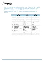
Страница 110: ...dement eau chaude Connessione Kanal tilslutning Duct connection Kanalanschluss Raccordement de gaine d air Connessione condotto mm 400 400 400 Vandtemperatur Water temperature Heizwasser temperatur Te...

Страница 111: ...asser Perte de charge sur l eau Perdita di carico acqua kPa 10 09 2 44 0 15 Modstand luft Pressure drop air Widerstand Luft Perte de charge sur l air Perdita di carico aria Pa 28 63 28 42 27 84 CDP 16...

Страница 112: ...it max Flusso max acqua l h 600 700 800 Max kapacitet Max capacity Max Heizleistung Puissance maxi Potenza max kW 4 0 4 5 5 5 Modstand Pressure drop Widerstand Perte de charge sur l eau de piscine Per...

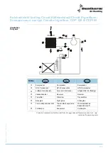
Страница 113: ...led condenser Luftgek hlter Verfl ssiger f V skebeholder Receiver Receiver g T rrefilter Filter drier Trockenfilter h Skueglas Sight glass Schauglas i Termo ekspansionsventil Thermostatic expansion va...

Страница 114: ...at HP BP Pressostato HP LP e Condenseur air Condensatore raffreddato ad aria f Bouteille liquide Sebatoio g D shydrateur Filtro a secco h Voyant liquide Obl d ispezione i D tendeur thermostatique Valv...

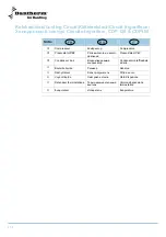
Страница 115: ...or Water cooled condenser Wassergek hler Verfl ssiger f Luftk let kondensator Air cooled condenser Luftgek hlter Verfl ssiger g V skebeholder Receiver Receiver h T rrefilter Filter drier Trockenfilter...

Страница 116: ...Compressore d Pressostat HP BP Pressostato HP LP e Condenseur eau Condensatore raffreddato ad acqua f Condenseur air Condensatore raffreddato ad aria g Bouteille liquide Sebatoio h D shydrateur Filtro...

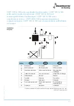
Страница 117: ...t HP LP pressostat e Luftk let kondensator Air cooled condenser Luftgek hlter Verfl ssiger f V skebeholder Receiver Receiver g T rrefilter Filter drier Trockenfilter h Skueglas Sight glass Schauglas i...

Страница 118: ...Nr No c Compresseur Compressore d Pressostat HP BP Pressostato HP LP e Condenseur air Condensatore raffreddato ad aria f Bouteille liquide Sebatoio g D shydrateur Filtro a secco h Voyant liquide Obl d...

Страница 119: ...stat HP LP pressostat HP LP pressostat e Vandk let kondensator Water cooled condenser Wassergek hler Verfl ssiger f Luftk let kondensator Air cooled condenser Luftgek hlter Verfl ssiger g V skebeholde...

Страница 120: ...con consendatore raffre Nr No c Compresseur Compressore d Pressostat HP BP Pressostato HP LP e Condenseur eau Condensatore raffreddato ad acqua f Condenseur air Condensatore raffreddato ad aria g Bou...

Страница 121: ...121 975672 Version 3 3 28 10 2010 Eldiagram Wiring diagram Schaltplan Sch ma lectrique Schema elettrico CDP 75 Diagram CDP 75 1 x 230 V 50 Hz CDP 75 1 x 230 50...

Страница 122: ...122 Eldiagram Wiring diagram Schaltplan Sch ma lectrique Schema elettrico CDP 125 Diagram CDP 125 1 x 230 V 50 Hz CDP 125 1 x 230 50...

Страница 123: ...123 975672 Version 3 3 28 10 2010 Eldiagram Wiring diagram Schaltplan Sch ma lectrique Schema elettrico CDP 125 CDP 165 Diagram CDP125 CDP 165 3 x 400 V 50 Hz CDP125 CDP 165 3 x 400 V 50...

Страница 124: ...124 Eldiagram Wiring diagram Schaltplan Sch ma lectrique Schema elettrico CDP 125 CDP 165 Diagram CDP125 CDP 165 3 x 230 V 50 Hz CDP125 CDP 165 3 x 230 V 50...

Страница 125: ...p inspek tionssiden Pushbutton ventilation on inspection side Druckknopf Ventilation auf der In spektions seite Bouton poussoir ventilation sur cot d inspection Interruttore ventilazione lato ispezio...

Страница 126: ...eservedele Spare parts Ersatzteile Pi ces de rechange Parti di ricambio CDP 75 CDP 75 1 230 V 50 Hz Illustration Forts ttes continued overleaf fortsetzt Suite la page suivante continua alla pagina seg...

Страница 127: ...t 11 524750 Membrantylle Diaphragm bush 12 069203 13 600027 Fordamperflade Evaporator 14 600026 Kondensatorflade Condenser 15 069197 16 069198 Styr for kondensator flade Guide for condenser coil 17 60...

Страница 128: ...r Safety switch 40 517594 Diodeprint Diode print 41 515081 Vippeafbryder Toggle switch 42 517596 Fladkabel til diodeprint Flat cable for diode 43 069206 44 602444 Driftkondensator Condenser 45 517597...

Страница 129: ...rdement d entr e 11 524750 Membrant lle Douille diaphragne 12 069203 13 600027 Verdampfer Evaporateur 14 600026 Verfl ssiger Condenseur 15 069197 16 069198 Steuer f r Verfl ssiger Guide du condenseur...

Страница 130: ...atine de diode 41 515081 Kippschalter Interrupteur basculant 42 517596 Flachkabel f r Diodenplatine Cable plat pour platine de diode 43 069206 44 602444 Betriebsverfl ssiger Condenseu 45 517597 W rmep...

Страница 131: ...llo lato sinistro 10a 068894 Itappo aspirazione 11 524750 Itappo aspirazione 12 069203 13 600027 Evaporatore 14 600026 Condensatore 15 069197 16 069198 Guida per batteria condensatore 17 602441 Compre...

Страница 132: ...trollo 38 517601 Etichetta pannello di controllo 39 521259 Interruttore di sicurezza 40 517594 Piastra diodi 41 515081 Interruttore a ginocchiera 42 517596 Cavo a nastro per piastra diodi 43 069206 44...

Страница 133: ...3 28 10 2010 Reservedele Spare parts Ersatzteile Pi ces de rechange Parti di ricambio CDP 125 CDP 125 3 400 V 50 Hz Illustration Forts ttes continued overleaf fortsetzt Suite la page suivante continua...

Страница 134: ...60 male Bottom plate 11 524750 Membrantylle DG11 Diaphragm bush DG11 12 600020 Fordamperflade Evaporator 13 600940 Kondensatorflade Condenser 14 069349 15 069348 16 601922 Kompressor Tecumseh TFH 55 C...

Страница 135: ...Man vre panel Operating panel 38 517601 Label for styrepanel Label for operating panel 39 521259 Sikkerhedsafbryder 3 polet Safety switch 40 517594 Diodeprint Diode print 41 515081 Vippeafbryder sort...

Страница 136: ...gauche 10a 069346 Bodenplatte T le de fond 11 524750 Membrant lle DG11 Douille diaphragne DG11 12 600020 Verdampfer Evaporateur 13 600940 Verfl ssiger Condenseur 14 069349 15 069348 16 601922 Kompres...

Страница 137: ...eau de man uvre 38 517601 Aufkleber f r Man vrierpaneel tiquette pour panneau de man uvre 39 521259 Sicherheitsschalter Coupe circuit de s curit 40 517594 Diodenplatine Platine de diode 41 515081 Kipp...

Страница 138: ...rna 10 293608 Pannello lato sinistro 10a 069346 Piastra di appoggio 11 524750 Boccola passacavo 12 600020 Evaporatore 13 600940 Condensatore 14 069349 15 069348 16 601922 Tecumseh TFH 55 Compressore T...

Страница 139: ...Dantherm 35b 560620 Pulsante in gomma 36 175348 37 069208 Pannello di controllo 38 517601 Etichetta pannello di controllo 39 521259 Interruttore di sicurezza 40 517594 Piastra diodi 41 515081 Interrut...

Страница 140: ...servedele Spare parts Ersatzteile Pi ces de rechange Parti di ricambio CDP 125 CDP 125 1 230 V 50 Hz Illustration Forts ttes continued overleaf fortsetzt Suite la page suivante continua alla pagina se...

Страница 141: ...12 600020 Fordamperflade Evaporator 13 600940 Kondensatorflade Condenser 14 069349 15 069348 16 601924 Kompressor FH 5524C kpl 230V Kompressor FH 5524C kpl 230V 16a 601923 Kompressor FH5524C Compresso...

Страница 142: ...sort 1 pol Toggle switch black 42 517596 Fladkabel til CDP diodeprint Flat cable for CDP diode print 43 069210 44 510340 Kontaktor CI 9 220 240V Contactor CI 9 220 240 V 46 517593 Printkort type CDG...

Страница 143: ...e DG11 Douille diaphragne DG11 12 600020 Verdampfer Evaporateur 13 600940 Verfl ssiger Condenseur 14 069349 15 069348 16 601924 Kompressor FH 5524C kpl 230 V Kompressor FH 5524C kpl 230 V 16a 601923 K...

Страница 144: ...chalter Interrupteur basculant 42 517596 Flachkabel f r CDP Diodenplatine Cable plat pour platine de diodes 43 069210 44 510340 Sch tz CI9 220 240V Contacteur CI 9 220 240 V 46 517593 Platine Typ CDG3...

Страница 145: ...rna 10 293608 Pannello lato sinistro 10a 069346 Piastra di appoggio 11 524750 Boccola passacavo 12 600020 Evaporatore 13 600940 Condensatore 14 069349 15 069348 16 601922 Compressore completo 16a 6019...

Страница 146: ...ontrollo 39 521259 Interruttore di sicurezza 40 517594 Piastra diodi 41 515081 Interruttore a ginocchiera 42 517596 Cavo a nastro per piastra diodi 43 069210 44 510340 CI 9 220 240V Contattore CI 9 22...

Страница 147: ...3 28 10 2010 Reservedele Spare parts Ersatzteile Pi ces de rechange Parti di ricambio CDP 165 CDP 165 3 400 V 50 Hz Illustration Forts ttes continued overleaf fortsetzt Suite la page suivante continua...

Страница 148: ...el left 10a 069346 Endebund Bottom plate 11 524750 Membrantylle DG11 Diaphragm bush DG11 12 600028 Fordamperflade Evaporator 13 600029 Kondensatorflade Condenser 14 069384 15 069348 16 602021 Kompress...

Страница 149: ...Label for styrepanel Label for operating panel 39 521259 Sikkerhedsafbryder 3 polet Safety switch 40 517594 Diodeprint Diode print 41 515081 Vippeafbryder sort 1 pol Toggle switch black 42 517596 Flad...

Страница 150: ...293614 Deckplatte links T le gauche 10a 069346 Bodenplatte T le de fond 11 524750 Membrant lle DG11 Douille diaphragne DG11 12 600028 Verdampfer Evaporateur 13 600029 Verfl ssiger Condenseur 14 069384...

Страница 151: ...u de man uvre 39 521259 Sicherheitsschalter Coupe circuit de s curit 40 517594 Diodenplatine Platine de diode 41 515081 Kippschalter Interrupteur basculant 42 517596 Flachkabel f r CDP Diodenplatine C...

Страница 152: ...tro esterna RAL 9016 10 293614 Pannello lato sinistro 10a 069346 Piastra di appoggio 11 524750 Boccola passacavo 12 600028 Evaporatore 13 600029 Condensatore 14 069384 15 069348 16 602021 MTZ 36 400V...

Страница 153: ...o di controllo 38 517601 Etichetta pannello di controllo 39 521259 Interruttore di sicurezza 40 517594 Piastra diodi 41 515081 Interruttore a ginocchiera 42 517596 Cavo a nastro per piastra diodi 43 0...

Страница 154: ...servedele Spare parts Ersatzteile Pi ces de rechange Parti di ricambio CDP 165 CDP 165 3 230 V 50 Hz Illustration Forts ttes continued overleaf fortsetzt Suite la page suivante continua alla pagina se...

Страница 155: ...panel left 10a 069346 Endebund Bottom plate 11 524750 Membrantylle DG11 Diaphragm bush DG11 12 600028 Fordamperflade Evaporator 13 600029 Kondensatorflade Condenser 14 069384 15 069348 16 602023 Kompr...

Страница 156: ...switch 40 517594 Diodeprint Diode print 41 515081 Vippeafbryder sort 1 pol Toggle switch black 42 517596 Fladkabel til CDP diodeprint Flat cable for CDP diode print 43 069210 44 510380 Kontaktor CI 16...

Страница 157: ...9016 10 293614 Deckplatte links T le gauche 10a 069346 Bodenplatte T le de fond 11 524750 Membrant lle DG11 Douille diaphragne DG11 12 600028 Verdampfer Evaporateur 13 600029 Verfl ssiger Condenseur 1...

Страница 158: ...40 517594 Diodenplatine Platine de diode 41 515081 Kippschalter Interrupteur basculant 42 517596 Flachkabel f r CDP Diodenplatine Cable plat pour platine de diodes 43 069210 44 510380 Sch tz CI9 220 2...

Страница 159: ...glia filtro esterna RAL 9016 10 293614 Pannello lato sinistro 10a 069346 Piastra di appoggio 11 524750 Boccola passacavo 12 600028 Evaporatore 13 600029 Condensatore 14 069384 15 069348 16 602023 MTZ...

Страница 160: ...lo 39 521274 Interruttore di sicurezza 40 517594 Piastra diodi 41 515081 Interruttore a ginocchiera 42 517596 Cavo a nastro per piastra diodi 43 069210 44 510380 CI 9 220 240V Contattore CI 9 220 240V...

Отзывы: