background image


Page 10 of 32 

Rev 0.95 

3.


Local control interface 

The local interface is a Beckhoff CP6706 Industrial PC with a touch sensitive monitor on which 
the HMI of the control system is displayed.  


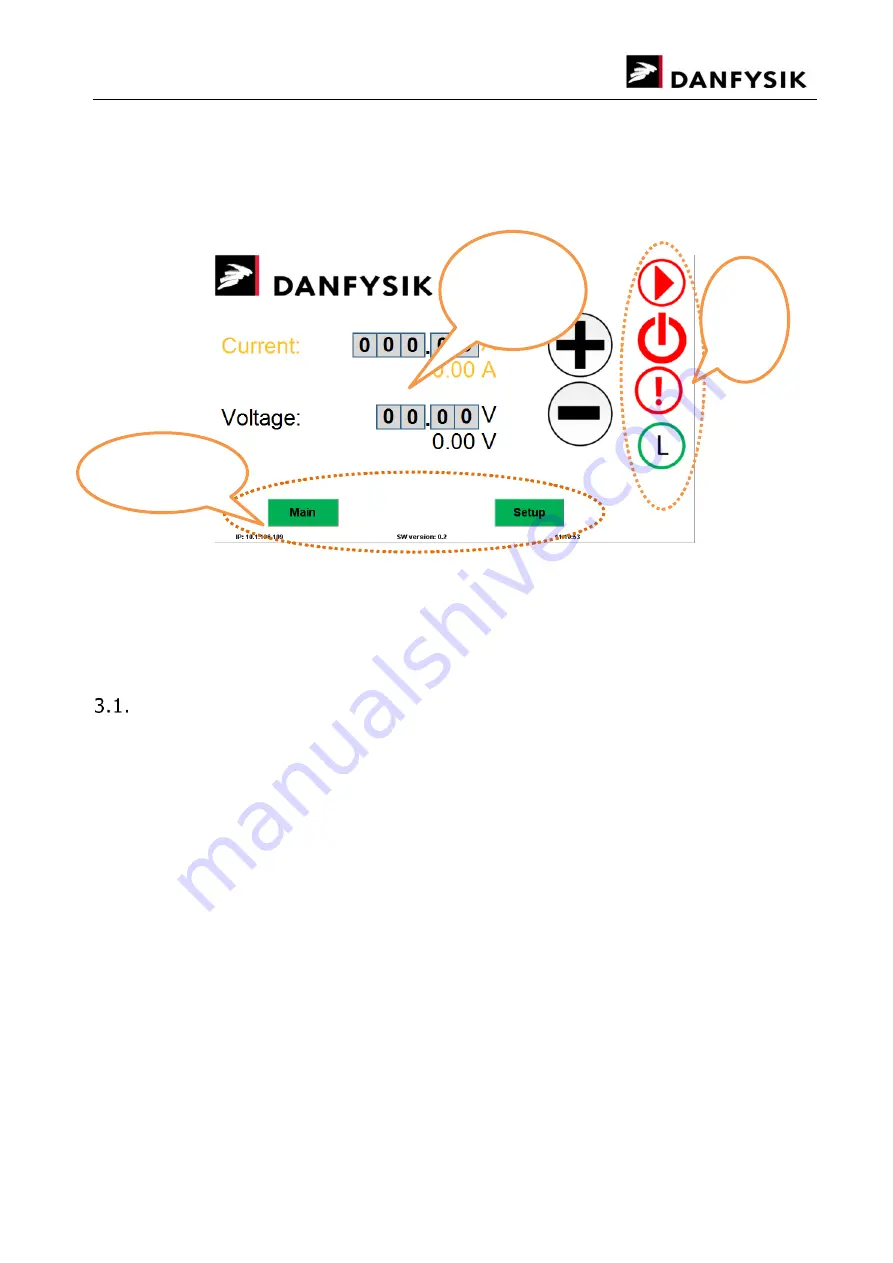
Figure 2: The main screen 

When the power supply is turned on, the operating system will boot up and show the main 

screen, please see Figure 2. The main screen consists of three main areas, the right-hand 
menu, bottom menu and the set and display area. In the bottom of the screen the IP address 

for remote connection can be seen as well as the version of the current software running on the 
PLC and the time of date. 


The right-hand menu 

The right-hand menu consists of four buttons and they are from the bottom the mode button, 
controlling the local/remote mode of the MPS, the interlock button, showing the interlock state, 
the standby button and the on button.  

3.1.1.


Changing the mode 

The control system can be in four command modes: Local, Local Locked, Remote and Remote 

Locked. When the system is in Local mode, the MPS can be controlled only from the local 
interface. It is possible to ask about status on the remote line but it is not possible to set values 

on the remote line. It is possible to switch to Remote mode from the local interface and also set 
it in Remote mode from the remote line. When the system is in Local Locked mode, the system 

can only be set in a different mode from the local interface. When the system is in Remote 
Locked mode, the system can only be set in a different mode from remote.  

When the system is in Remote mode it is possible to set values over the remote line and the 

values will be displayed on the local interface but it is not possible set values from the local 
interface.  

3.1.2.


Interlocks and warnings  

All interlocks and warnings are displayed in the interlock list, which can be accessed by pressing 
the interlock button in the right-hand menu. When there is an interlock, the interlock button is 

red, when there are only warnings the button is yellow. All interlocks are latched, meaning they 
will only be reset and disappear from the list after a Reset command has been issued or the 

reset button, depending on what mode the MPS is in. Warnings are not latched and are 

Right 

hand 

menu 

Bottom menu 

Set and 

display 

area 

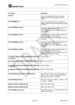
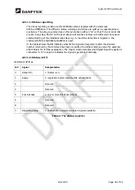
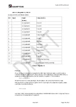
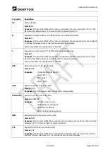
Содержание SYSTEM 8700

Страница 1: ...32 Preparation Review Signature Date Author Per M rkegaard Hansen PMH TSS 27 11 2017 Check Thomas Bay Approved by TSS 23 11 2017 Tomas Bruunshuus S rensen SYSTEM8700 User s Manual Manual for setup and...

Страница 2: ...from digi loop card 27 11 2017 0 95 PMH Added the SYSTem LOCK LREQuest SCPI command Added the two warnings Pre trig fault and polarity signal missing Danfysik A S Gregersensvej 8 DK 2630 Taastrup Denm...

Страница 3: ...on 11 3 1 4 Turn the Power Supply Off 11 SETTING A CURRENT OR VOLTAGE 12 SETTINGS 13 THE LOGIN SCREEN 14 ADVANCED SETTINGS 14 3 5 1 The interlock file 14 3 5 2 Editing the files 15 4 REMOTE CONTROL I...

Страница 4: ...Page 4 of 32 Rev 0 95 PREVENTIVE MAINTENANCE 31 ADJUSTMENT AND CALIBRATION 31 6 SPARE PARTS ORDERING OF 32 HANDLING ESD SENSITIVE COMPONENTS 32...

Страница 5: ...warnings Please review the following safety precautions and all warning and caution information throughout the manual WARNING This Magnet Power Supply MPS is intended for professional incorporation in...

Страница 6: ...vice engineers responsible for the installation maintenance and repair of the Power Supplies using SYSTEM8700 control system supplied by Danfysik A S The power supply itself and its regulation system...

Страница 7: ...e defective or unworkable due to mishandling improper maintenance incorrect use radiation damage or any other circumstance not generally acceptable for equipment of a similar type On standard products...

Страница 8: ...gent and a full report of the damage should be forwarded to DANFYSIK A S or our local agent representative immediately Upon receipt of this report you will be issued instructions for the repair replac...

Страница 9: ...nections to the PLC Instructions for remote line setup and use are given in chapter 4 2 4 3 Connection of External Interlocks Interlocks externals as well as internals are connected to the control sys...

Страница 10: ...d only from the local interface It is possible to ask about status on the remote line but it is not possible to set values on the remote line It is possible to switch to Remote mode from the local int...

Страница 11: ...be executed 1 Set the system in Local mode by pressing the mode button in the right hand panel and pressing L 2 Make sure that there are no faults Faults are indicated with a red FAULT button in the...

Страница 12: ...ater is changed as soon as the digit is changed The current is set and read in amps by default but the software can be configured to use PPM for the set current in the setup screen When the digit is c...

Страница 13: ...set to Voltage an extra input field appears on the front page allowing to also set a voltage Note that this is only possible for power supplies with implemented voltage control loop in the regulation...

Страница 14: ...gs are for advanced use only Use of strict syntax is important for the stability of the control system 3 5 1 The interlock file The interlock file controls the setup of interlocks what text should be...

Страница 15: ...spaces in the file 3 5 2 Editing the files Basically there are two ways to edit the file FTP Use a normal FTP client to connect to the PLCs IP address and use the user name Danfysik and password Danf...

Страница 16: ...ing it much easier to implement different instruments in software Most SCPI commands but not all have set version and an ask version Example The command OUTP CURR 22 56 sets the current to 22 56 amps...

Страница 17: ...he warning interlock bit the exact mapping is listed in Table 6 STATus OPERation REG4 Returns the Status operations REG4 register bits as a decimal number These are the warning interlock bit from the...

Страница 18: ...This event is only implemented as a query SYSTem LOCK LREQuest The command attempts to set the system in remote locked mode The system must be in remote mode to allow this operation This event is onl...

Страница 19: ...TATus QUEStionable REG1 is used In the tables below the Bit indicates what bit the signal corresponds to after the decimal number returned by the command has been converted to a binary digit see also...

Страница 20: ...used 1 Not used 2 Not used 3 Not used 4 Not used 5 Not used 6 Not used 7 Not used 8 Sum interlock 9 Not used 10 REG1 Sum bit for register 1 see below 11 REG2 Sum bit for register 2 see below 12 REG3 S...

Страница 21: ...erload 7 eIL_Sum Sum interlock 8 eIL_WaterTempIntl Water temperature interlock 9 eIL_WaterTempWarn Water temperature warning 10 eIL_WaterFlowIntl Water flow interlock 11 eIL_WaterFlowWarn Water flow w...

Страница 22: ...erpretation default configuration 0 bInterlock2_1 eIL_Interlock3_01 Magnet over temp 1 bInterlock2_2 eIL_Interlock3_02 Magnet flow interlock 2 bInterlock2_3 eIL_Interlock3_03 External 1 3 bInterlock2_...

Страница 23: ...oard13 Polarity signal missing warning Table 7 Register 4 Example If e g we have an interlock connected to the first input module module 1 and the wire is connected to the modules input 5 this is what...

Страница 24: ...Range 999999 to 999999 8 same as channel 0 16 same as channel 0 DA read Queries the setvalue DAC value from the PLC Format DA ch where ch is the decimal channel number Available channels 0 current in...

Страница 25: ...therwise error 5 is returned Cannot execute command The S1H will reflect the resulting status of the MPS VER Returns the version of the MPS firmware Format VER Response Copyright DANFYSIK A S 2017 Sys...

Страница 26: ...PLC and OK is returned Otherwise error 5 is returned Cannot execute command S3H Format S3H Queries the status on MPS Response XXXX X hexadecimal character See section 4 3 2 2 for individual bits Table...

Страница 27: ...19 eIL_Interlock2_03 20 Overload 1 overload detected 21 Pull up power failure 1 failure present 22 Soft start failure 1 failure present 23 Polarity switch failure 1 failure present 24 PLC module failu...

Страница 28: ...Not used Always 0 13 Not used Always 0 14 Not used Always 0 15 Not used Always 0 Additional remote access 4 4 1 Remote Desktop The normal Remote Desktop is not supported on Windows CE Instead a speci...

Страница 29: ...supply s IP address can be done on the local control or via Cerhost Click on Start button and select Control Panel Select the Network and Dial up Connections Open the network properties for the networ...

Страница 30: ...return and line feed characters 0D 0A must be used as stop character please see Figure 11 Figure 11 The Hercules utility from HW Group Further information on Hercules and a download link can be found...

Страница 31: ...lectrical supply Always ensure by using a suitable measuring device that no voltage is present prior to commencing work Preventive maintenance In a normal operating environment perform the following t...

Страница 32: ...ed directly via www dfservice dk rma Please include the following information in your request Magnet Power Supply type e g MPS 854 The serial number of the unit See the data label on the front door Th...

Отзывы: