


4.2 Encoder
4.2.1 Permissible Encoder Cable Length
The permissible cable length depends on the selected
encoder. The longest cable can be achieved when using
bipolar TTL encoders.
Unipolar HTL encoders only permit a shorter length. In this
case, the encoder power supply voltage plays a decisive
role.
The maximum cable length for HTL encoders used as
unipolar encoder (in this case only one signal is evaluated)
is 100 m.
The maximum cable length for TTL encoders used as
bipolar encoder (in this case both signals A/nA or B/nB) is
150 m.
The minimum cross-section of the power supply conductor
is 0.75 mm
2
.
NOTICE
Routing of the sensor cables
All proximity switch sensor/encoder cables must be
screened when laid. The screen must be connected to
chassis at both ends. Always connect chassis on the
rotary encoder to chassis on the frequency converter.
CAUTION
The sensor connections must not be plugged in or
pulled off during operation. This could damage the
electrical components of the encoder. Always de-
energise connected encoders and the safety option
before plugging in or pulling off encoder connections.
Lines twisted in pairs for signal transmission according
to RS-485 standard must be used for data signals or
track A and track B. The wire cross section must in each
individual case be chosen in compliance with the current
consumption of the encoder and the cable length
required for the installation.
Diagnostics are performed on the encoder input signals. If
the encoder diagnostic tests fail, an error 99 (Safe State
fault) occurs.
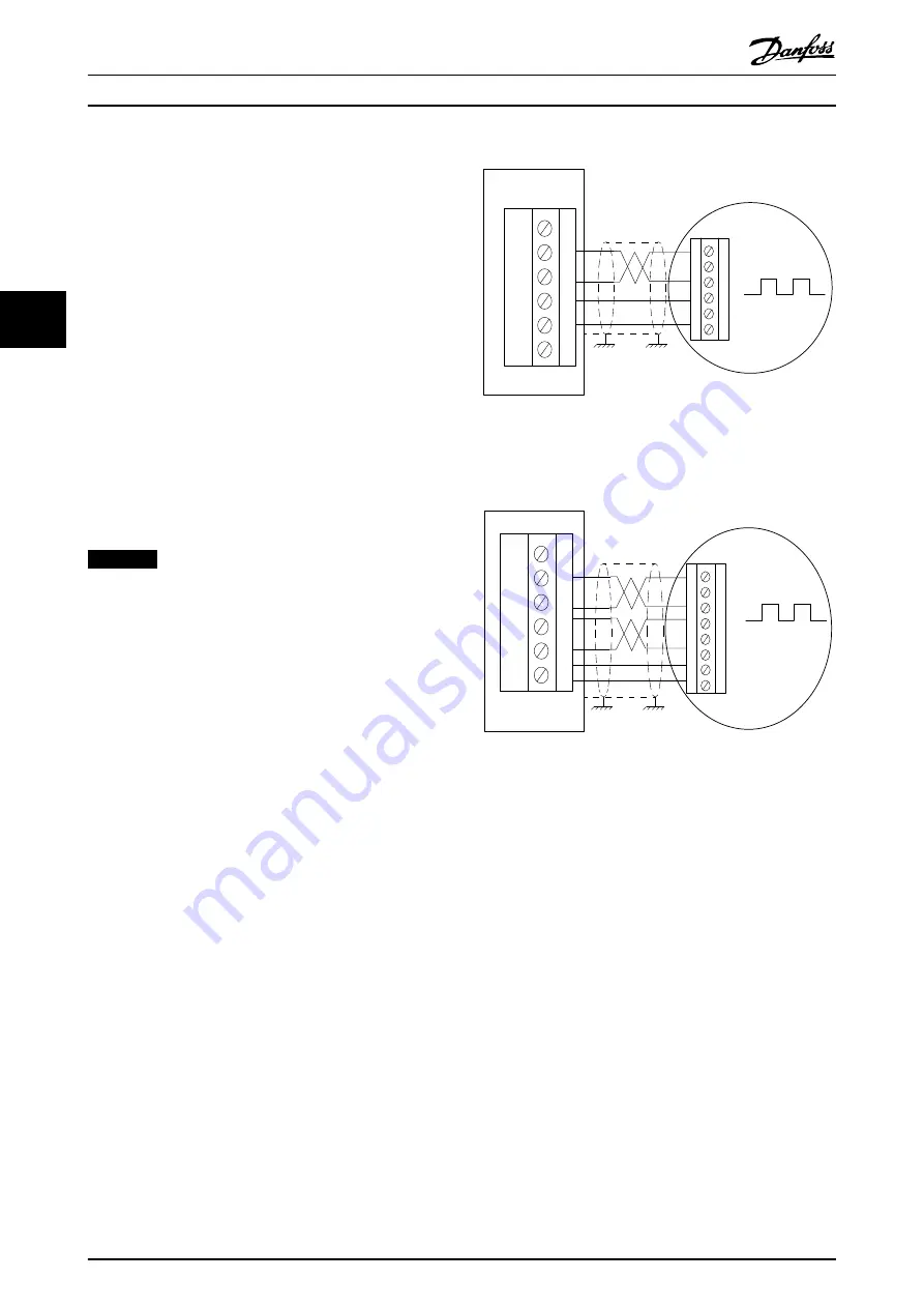
4.2.2 Encoder Wiring Examples
and
show examples of how to
connect encoder power and encoder signals.
130BC374.11
A
B
24V
GND
4
7
10
11
FC302
MCB151
Illustration 4.7 Y31/ Connecting Power and Encoder Signals to
HTL Encoder (MCB 151)
130BC375.11
A
B
24V
GND
4
7
10
11
nA
6
nB
9
FC302
MCB150
Illustration 4.8 Y30/ Connecting Power and Differential
Encoder Signals to TTL Encoder (MCB 150)
shows TTL encoder with 24 V supply and
TTL output. If an encoder for 5 V supply must be
connected, use a 5 V external supply.
4.2.3 Proximity Switch
An inductive proximity switch, detecting already present
mechanical parts, e.g. a gear wheel, is a frequently used
alternative to standard encoders. The required minimum
number of pulses per revolution (ppr) is 2 on the motor
shaft while considering the gear ratio.
Installation
Operating Instructions
30
Danfoss A/S © Rev. 2014-02-11 All rights reserved.
MG34W302
4
4