


3 Center Winder Control
3.1 Introduction
Center winders are widely used in the processing of
materials such as cloth, plastics, paper, and sheet metal.
Center winder control is to maintain a stable tension on
the line or web of the material during the winding process.
Instable tension may cause physical deformities of the
material. Because the diameter of the roll changes
constantly, the winding or unwinding speed must be
adapted to maintain a stable tension.
Control principle
The center winder control in FC 360 uses a speed-based method with tension feedback. The tension feedback is provided
by either a load cell or a dancer.
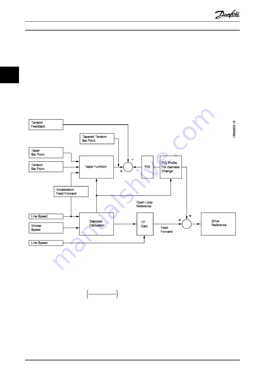
shows the control diagram of a center winder system.
Illustration 3.1 Control Diagram of a Center Winder System
The center winder control calculates the roll diameter and feed the frequency converter with an open-loop speed reference.
A PID amplifier compares the actual tension feedback with the tapered tension setpoint, and generates a speed signal
based on the error. The speed signal is aggregated with the speed reference signal to determine the actual winder speed.
Roll
diameter
=
core
diameter
Line
speed
Winder
speed
This calculation needs to be performed fast, because the diameter of the roll changes faster when the roll is near the core. If
the actual diameter changes faster than the diameter is calculated, the open-loop reference speed lags too far behind the
required speed, and the tension PID will need to make up too much of the difference.
The tension PID updates every 16 ms. The calculated diameter is used by both the open-loop reference and as an input to
the tension PID.
Center Winder Control
VLT
®
AutomationDrive FC 360
6
Danfoss A/S © 11/2014 All rights reserved.
MG06E102
3
3