


130BE998.10
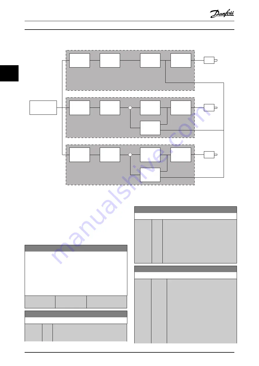
Set-point
Calculation
External Set-point
Ramp
Droop
Speed
PID
Torque
PID
M2
M3
VLT 2
VLT 3
Set-point
Calculation
Ramp
Droop
Speed
PID
-
Set-point
Calculation
Ramp
Speed
PID
Torque
PID
M1
VLT 1
-
Torque
PID
Illustration 3.48 Speed Trim
shows a single source set-up where the
master sends the torque signal to all followers. The
number of available analog outputs on the master limits
this set-up. To overcome the limitation of the number of
analog outputs, use a cascade principle. The cascade
principle makes the control slower and less accurate
compared with the set-up using analog outputs.
7-01 Speed PID Droop
The droop function allows the frequency converter to decrease
the motor speed proportional to the load. The droop value is
directly proportional to the load value. Use the droop function
when several motors are mechanically connected and the load
on motors can differ.
Ensure that
parameter 1-62 Slip Compensation
has a default
setting.
Range:
Function:
0 RPM
*
[0 - 200 RPM]
Enter the droop value at
100% load.
7-02 Speed PID Proportional Gain
Range:
Function:
Size
related
*
[0 -
1 ]
Enter the speed controller proportional gain.
The proportional gain amplifies the error (that
is the deviation between the feedback signal
7-02 Speed PID Proportional Gain
Range:
Function:
and the setpoint). This parameter is used with
parameter 1-00 Configuration Mode
[0] Speed
open loop
and
[1] Speed closed loop
control.
Quick control is obtained at high amplification.
Increasing amplification makes the process less
stable.
For values with 4 decimals, use
parameter 30-83 Speed PID Proportional Gain
.
7-03 Speed PID Integral Time
Range:
Function:
Size
related
*
[1.0 -
20000
ms]
Enter the speed controller integral time,
which determines the time the internal PID
control takes to correct errors. The greater
the error, the more quickly the gain
increases. The integral time causes a delay
of the signal and therefore a dampening
effect and can be used to eliminate steady-
state speed error. Obtain quick control
through a short integral time, though if the
integral time is too short, the process
becomes unstable. An excessively long
integral time disables the integral action,
Parameter Descriptions
VLT
®
AutomationDrive FC 301/302
146
Danfoss A/S © 10/2018 All rights reserved.
MG33MP02
3
3
Содержание VLT AutomationDrive FC 302
Страница 2: ......