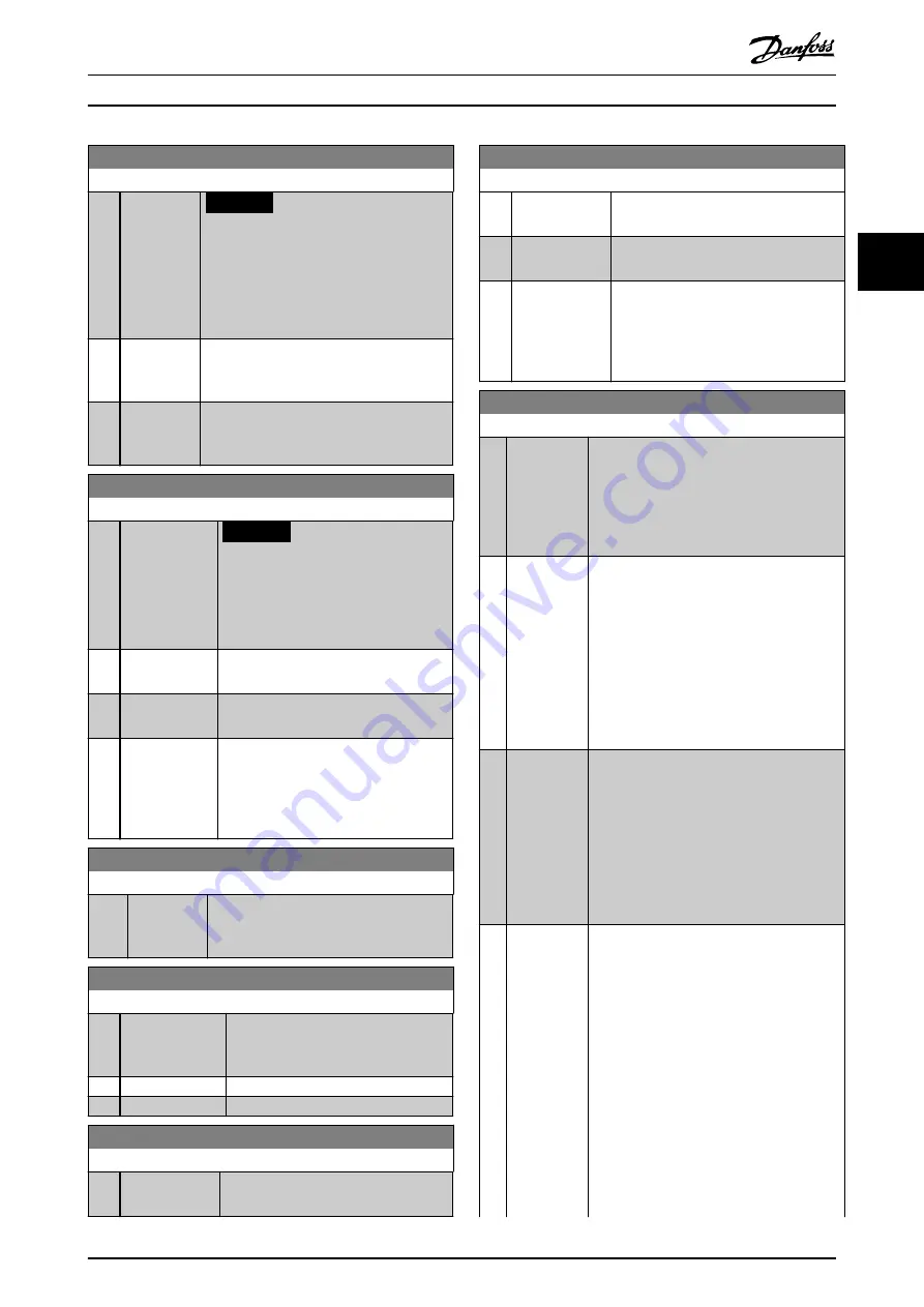
5-71 Term 32/33 Encoder Direction
Option:
Function:
NOTICE
This parameter cannot be adjusted
while the motor is running.
Change the detected encoder rotation
direction without changing the wiring to the
encoder.
[0]
*
Clockwise
Sets channel A 90° (electrical degrees)
behind channel B upon clockwise rotation of
the encoder shaft.
[1]
Counter
clockwise
Sets channel A 90° (electrical degrees) ahead
of channel B upon clockwise rotation of the
encoder shaft.
5-72 Term 32/33 Encoder Type
Option:
Function:
NOTICE
This parameter is only available
with software version 48.XX.
Select the signal type of the encoder
connected to terminals 32, 33.
[0]
*
Quadrature A/B
Format
Encoder with 2 tracks: A and B, displaced
90
°
for detecting the rotational direction.
[1]
Single Channel
33
Encoder with 1 track connected to
terminal 33.
[2]
Signle Channel
w/Dir.
Encoder with 1 track connected to
terminal 33. The direction is set with a
signal on terminal 32: 0 V = forward/
clockwise, 24 V = reverse/counter
clockwise.
5-75 Term 27/29 Pulses Per Revolution
Range:
Function:
1024
*
[1 - 16384 ] Set the resolution of the encoder
connected to terminal 27/29 in pulses per
revolution.
5-76 Term 27/29 Encoder Direction
Option:
Function:
Change the detected encoder rotation
direction without changing the wiring
to the encoder.
[0]
*
Clockwise
[1]
Counter clockwise
5-77 Term 27/29 Encoder Type
Option:
Function:
Select the signal type of the encoder
connected to terminal 27/29.
5-77 Term 27/29 Encoder Type
Option:
Function:
[0]
*
Quadrature A/B
Encoder with 2 tracks: A and B, displaced
90° for detecting the rotational direction.
[1]
Single Channel
29
Encoder with 1 track connected to
terminal 29.
[2]
Single Channel
w/Dir
Encoder with 1 track connected to
terminal 29. The direction is set with a
signal on terminal 27: 0 V = forward/
clockwise, 24 V = reverse/counter
clockwise.
5-78 Term 27/29 Encoder Sim
Option:
Function:
Select the source for generation of the
encoder simulation output. To enable 24V
encoder simulation on terminal 27/29, set
parameter 5-30 Terminal 27 Digital Output
and
parameter 5-31 Terminal 29 Digital Output
must be set to
[54] 24V Encoder Sim
.
[1]
*
Actual
Position
The encoder simulation is a mirror of actual
position. The output is scaled by
parameter 5-75 Term 27/29 Pulses Per
Revolution
related to 1 motor revolution. One
motor revolution is represented by the
number of pulses set in
. This means that
one motor revolution is represented by the
number of pulses set in
.
[2] Commanded
Position
The encoder simulation is a mirror of
commanded position (position set point for
the position PI controller). The output is
scaled by
parameter 5-75 Term 27/29 Pulses
related to one motor
revolution. This means that one motor
revolution is represented by the number of
pulses set in
parameter 5-75 Term 27/29 Pulses
[3] Vir. Master
Position
The encoder simulation is generated by the
virtual master function. The output is scaled
by
parameter 5-75 Term 27/29 Pulses Per
. Virtual master speed reference can
be set by fieldbus REF 1 or the source
selected in
parameter 3-16 Reference Resource
relative to
. Example: With 3-27 = 50Hz and a
reference of 50% the output corresponds to a
master speed of 50Hz*60sec/min*
50%=1500RPM. The pulse frequency will be
parameter 5-75 e.g. 1024 * 1500RPM/60 =
25.6kHz.
Speed of the individual followers is
determined by their scaling in parameters
Parameter Descriptions
Programming Guide
MG33MP02
Danfoss A/S © 10/2018 All rights reserved.
133
3
3
Содержание VLT AutomationDrive FC 302
Страница 2: ......


