


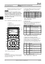
The direction of rotation can be changed by switching two
phases in the motor cable or by changing the setting of
parameter 4-10 Motor Speed Direction
.
Motor rotation check can be performed via
parameter 1-28 Motor Rotation Check
and following the
steps shown in the display.
175HA036.11
U
1
V
1
W
1
96
97
98
FC
Motor
U
2
V
2
W
2
U
1
V
1
W
1
96
97
98
FC
Motor
U
2
V
2
W
2
Figure 4.4 Motor Rotation Check
F-frame requirements
Use motor phase cables in quantities of 2, resulting in 2, 4,
6, or 8 to obtain an equal number of wires on both
inverter module terminals. The cables are required to be
equal length within 10% between the inverter module
terminals and the first common point of a phase. The
recommended common point is the motor terminals.
Output junction box requirements
The length, a minimum of 8 ft [2.5 m], and quantity of
cables must be equal from each inverter module to the
common terminal in the junction box.
NOTICE!
If a retrofit application requires an unequal number of
wires per phase, consult the factory or use the top/
bottom entry side cabinet option, instruction 177R0097.
4.6.2 Brake Cable
Adjustable frequency drives with factory installed brake
chopper option
(Only standard with letter B in position 18 of type code).
The connection cable to the brake resistor must be
shielded and the max. length from adjustable frequency
drive to the DC bar is limited to 82 ft [25 m].
Terminal No.
Function
81, 82
Brake resistor terminals
Table 4.3 Terminal Functions
The connection cable to the brake resistor must be
shielded. Connect the shield with cable clamps to the
conductive backplate of the adjustable frequency drive
and the metal cabinet of the brake resistor.
Size the brake cable cross-section to match the brake
torque. See also
Brake Instructions
for further information
regarding safe installation.
WARNING
Note that voltages up to 790 V DC, depending on the
supply voltage, are possible on the terminals.
F-frame requirements
The brake resistors must be connected to the brake
terminals in each inverter module.
4.6.3 Motor Insulation
For motor cable lengths
≤
the maximum cable length, the
motor insulation ratings listed in
are
recommended. The peak voltage can be twice the DC link
voltage or 2.8 times AC line voltage, due to transmission
line effects in the motor cable. If a motor has lower
insulation rating, use a dU/dt or sine-wave filter.
Nominal AC Line Voltage
Motor Insulation
U
N
≤
420 V
Standard U
LL
= 1,300 V
420 V < U
N
≤ 500 V
Reinforced U
LL
= 1,600 V
Table 4.4 Recommended Motor Insulation Ratings
Electrical Installation
Installation Manual
MG37A322
Danfoss A/S © Rev. 04/2015 All rights reserved.
39
4
4
Содержание VLT AutomationDrive FC 302
Страница 2: ......
Страница 127: ...Index Installation Manual MG37A322 Danfoss A S Rev 04 2015 All rights reserved 125...