


To minimise the overshoot,
7-03 Speed PID Integral Time
could be set to approx. 2.5 s (varies with the application).
Set
7-04 Speed PID Differentiation Time
to 0 until everything
else is tuned. If necessary, finish the tuning by experi-
menting with small increments of this setting.
3.6.6.3 Process PID Control
Use the Process PID Control to control application
parameters that can be measured by a sensor (i.e.
pressure, temperature, flow) and be affected by the
connected motor through a pump, fan or otherwise.
shows the control configurations where the
Process Control is possible. When a Flux Vector motor
control principle is used, take care also to tune the Speed
Control PID parameters. Refer to
to see
where the Speed Control is active.
1-00 Configu-
ration Mode
1-01 Motor Control Principle
U/f
VVC
+
Flux
Sensorless
Flux w/
enc. feedb
[3] Process
Not
Active
Process
Process &
Speed
Process &
Speed
Table 3.4 Control Configurations with Process Control
NOTICE
The Process Control PID works under the default
parameter setting, but tuning the parameters is highly
recommended to optimise the application control
performance. The 2 Flux motor control principles are
specially dependant on proper Speed Control PID tuning
(before tuning the Process Control PID) to yield their full
potential.
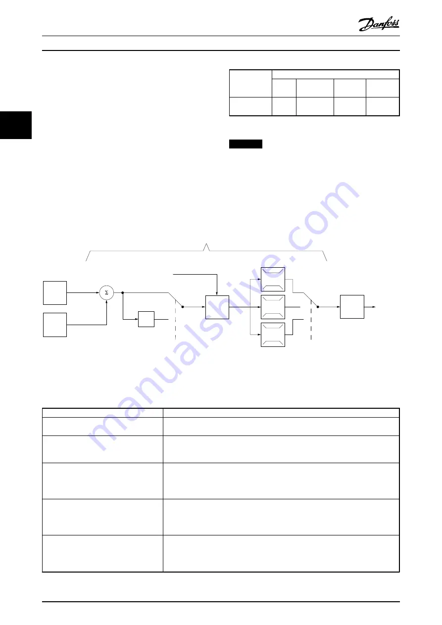
P 7-30
normal/inverse
PID
P 7-38
*(-1)
Feed forward
Ref.
Handling
Feedback
Handling
% [unit]
% [unit]
%
[unit]
%
[speed]
Scale to
speed
P 4-10
Motor speed
direction
To motor
control
Process PID
130BA178.10
_
+
0%
-100%
100%
0%
-100%
100%
Illustration 3.9 Process PID Control Diagram
sums up the characteristics that can be set up for the process control.
Parameter
Description of function
7-20 Process CL Feedback 1 Resource
Select from which Source (i.e. analog or pulse input) the Process PID should get its
feedback
7-22 Process CL Feedback 2 Resource
Optional: Determine if (and from where) the Process PID should get an additional
feedback signal. If an additional feedback source is selected, the 2 feedback signals are
added together before being used in the Process PID Control.
7-30 Process PID Normal/ Inverse Control
Under
[0] Normal operation
, the Process Control responds with an increase of the motor
speed, if the feedback is getting lower than the reference. In the same situation, but
under
[1] Inverse operation
, the Process Control responds with a decreasing motor speed
instead.
7-31 Process PID Anti Windup
The anti-windup function ensures that when either a frequency limit or a torque limit is
reached, the integrator is set to a gain that corresponds to the actual frequency. This
avoids integrating on an error that cannot in any case be compensated for with a speed
change. This function can be disabled by selecting
[0] Off
.
7-32 Process PID Start Speed
In some applications, reaching the required speed/set point can take a very long time. In
such applications it might be an advantage to set a fixed motor speed from the frequency
converter before the process control is activated. This is done by setting a Process PID
Start Value (speed) in
7-32 Process PID Start Speed
.
Basic Operating Principles
VLT
®
AutomationDrive FC 301/FC 302 Design Guide, 0.25-75 kW
26
MG33BF02 - Rev. 2013-12-20
3
3
Содержание VLT AutomationDrive FC 301
Страница 2: ......
Страница 199: ...Index VLT AutomationDrive FC 301 FC 302 Design Guide 0 25 75 kW MG33BF02 Rev 2013 12 20 197...