


35
Wiring
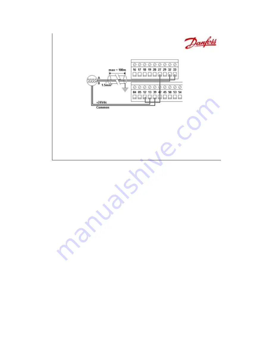
• Digital Inputs – Encoder
– A Channel showing speed comes into term 33 (P 307)
– B Channel showing direction comes into term 32 (P 306)
– +24Vdc power from terminal 13, common terminal 39
– P 329 sets PPR for Encoder
– P 345 sets loss timeout, P 346 sets loss function
Encoder
For a Speed Closed Loop application, the encoder is wired directly into the control
section. Terminal 33 is set for the A channel, which indicates speed, and terminal 32 is set
for the B channel, which is 90° out of phase and indicates direction. +24Vdc Power for the
encoder comes from terminals 12 or 13, and common is wired to terminal 39. Only terminals
33 and 32 can be wired for an encoder. This arrangement must use +24Vdc, 5Vdc used on
many encoders does not operate indicate a signal to the drive.
Parameter 329 sets the pulse per revolution, PPR, for the encoder, from 128ppr up
to 4096ppr. By default it goes to 1024ppr. Parameter 345 sets the amount of time (0-60sec)
the drive is to wait before it indicates that the encoder has lost its signal and that there is an
error. Parameter 346 indicates what the drive does upon a loss of the encoder signal. By
default it goes to OFF.
The next section covers Analog Inputs.