


Conversion
index
Conversion
factor
73
0.1
2
100
1
10
0
1
-1
0.1
-2
0.01
-3
0.001
-4
0.0001
-5
0.00001
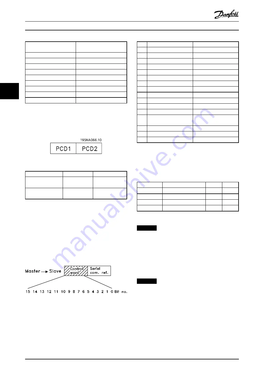
4.7.5 Process Words
The block of process words is divided into 2 blocks of 16
bits, which always occur in the defined sequence.
Illustration 4.28 Block of Process Words
PCD 1
PCD 2
Control telegram
(master
⇒
slave)
Control word
Reference-value
Control telegram
(slave
⇒
master)
Status word
Present output
frequency
Table 4.10 Function of PCD 1 and PCD 2
4.7.6 Control Word According to FC
Protocol
To select
FC protocol
in the control word, set
parameter
512 Telegram Profile
to
[1] FC protocol
.
The control word is used to send commands from a master
(e.g. a PC) to a slave (frequency converter).
Illustration 4.29 Control Word According to FC Protocol
Bit
Bit=0
Bit=1
00
Preset ref. lsb
01
Preset ref. msb
02
DC braking
03
Coasting stop
04
Quick stop
05
Freeze outp. freq.
06
Ramp stop
Start
07
Reset
08
Jog
09
Ramp 1
Ramp 2
10
Data not valid
Data valid
11
No function
Relay 01 activated
12
No function
Digital output Terminal 46
activated
13
Select Setup, lsb
14
Select Setup, msb
15
Reversing
Table 4.11 Bit Definition
Bit 00/01
Bit 00/01 is used to select between the 4 pre-programmed
references (
parameters 215-218 Preset reference
) according
to
.
Preset ref.
Parameter
Bit 01
Bit 00
1
215
0
0
2
216
0
1
3
217
1
0
4
218
1
1
Table 4.12 Bit 00/01
NOTICE
In
parameter 508 Selection of preset reference
, a selection
is made to define how bit 00/01 gates with the
corresponding function on the digital inputs.
Bit 02, DC brake
Bit 02='0' causes DC braking and stop. Brake voltage and
duration are preset in
parameters 132 DC brake voltage
and
126 DC braking time
.
NOTICE
In
parameter 504 DC brake
, a selection is made to define
how bit 02 gates with the corresponding function on a
digital inpu
Bit 03, Coasting stop
Bit 03='0' causes the frequency converter to immediately
release the motor (the output transistors are shut off), so
that it coasts to a standstill.
Bit 03='1' causes the frequency converter to be able start
the motor if the other starting conditions have been
fulfilled.
Programming
Design Guide
110
Danfoss A/S © Rev. May/2014 All rights reserved.
MG27E402
4
4


