•
•
•
is impacted. Alarms or faults are triggered in the drive to notify customers or service technicians. Some of the corrective actions
include replacement of faulty motors or bearings and ensuring the motor is running within optimal conditions.
The following are the monitoring capabilities introduced:
Motor stator winding monitoring:
During monitoring, an inter-turn short circuit or imbalance in the motor winding is detected
in advance. Damage caused by motor stator winding isolation occurs over time. When more winding turns are impacted, the
excessive heating activates the overcurrent protection, which stops the motor.
Vibration monitoring:
With the help of external sensors, the drive can monitor vibration levels in a motor. Vibrations affect
motor control and can lead to motor failure. During monitoring, motor misalignment is detected early and wear and tear of
mechanical parts is identified earlier.
NOTE!
The ISO 10816 standard provides guidance for evaluating vibration severity for machines operating within the 10–200 Hz
frequency range. The standard must be complied with before commissioning the vibration monitoring function.
Load envelope:
Mechanical load of an application is monitored by comparing the current load curve with the expected load
curve based on data gathered during commissioning. During monitoring, overload and underload deviations which occur in
applications are detected.
Load monitoring
St
at
or
w
in
di
ng
fa
ul
t d
et
ec
tio
n
El
ec
tr
ic
m
ot
or
fa
ul
ts
,
e.
g.
w
in
di
ng
s
M
ec
h
m
ot
or
fa
ul
ts
,
e.
g.
b
ea
rin
gs
M
ec
ha
ni
c
fa
ul
t e
.g
.
Sh
af
t m
is
al
ig
nm
en
t
A
pp
lic
at
io
n
sp
ec
ifi
c
fa
ul
t e
.g
. C
lo
gg
ed
pu
m
p
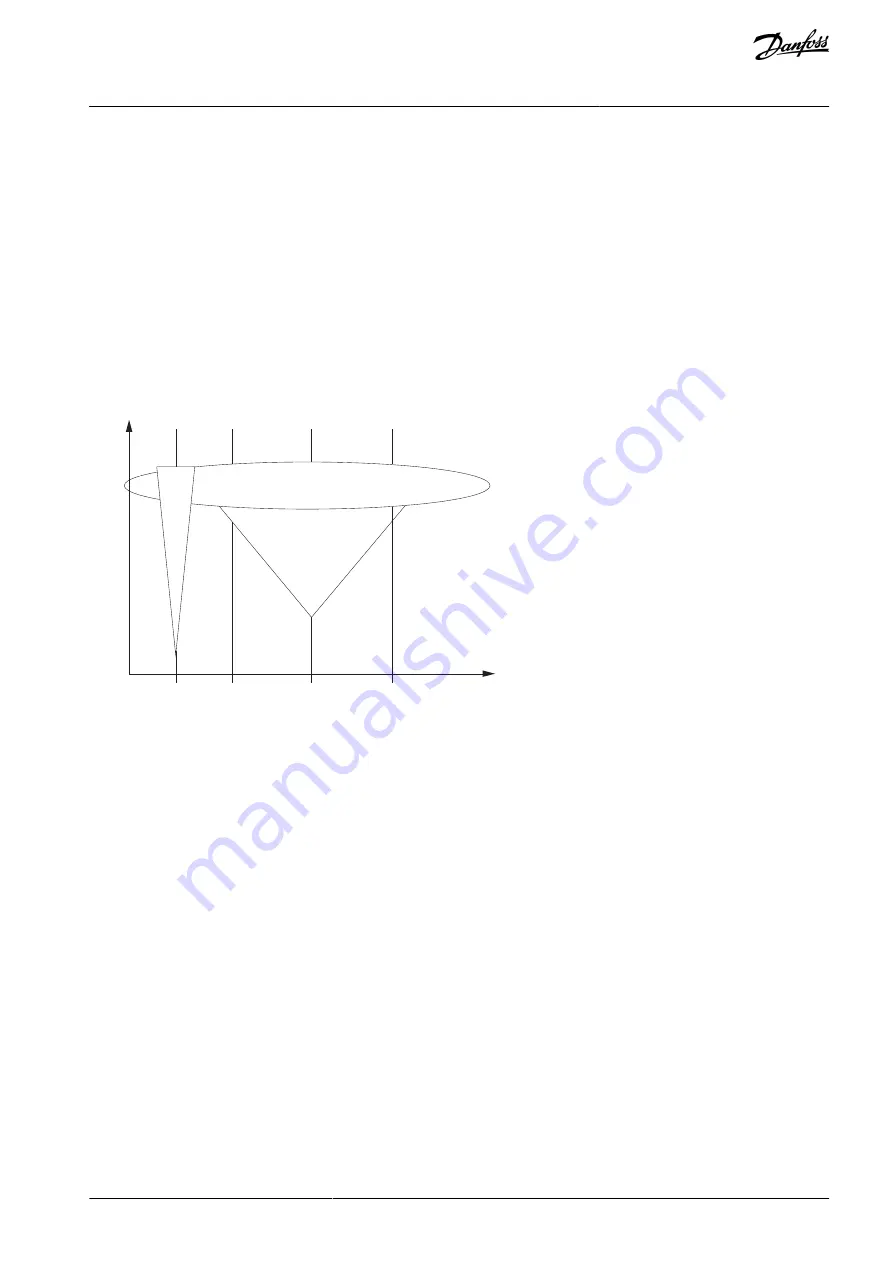
Vibration levels (RMS)
monitoring
Sensitivity of deduction methods (qualitative)
Fault
severity
Fault types
e3
0b
i5
57
.1
0
Illustration 105: Condition-based Monitoring
To begin Condition-based Monitoring, a baseline must be generated. During this activity, the system captures motor stator winding
speed points for each baseline. Define the duration and the minimum and maximum speeds for baseline generation. During base-
line generation, 10 speed points are captured. The first and last speed point is captured based on the defined minimum and maxi-
mum speeds respectively.
If speed points are not captured properly, baseline generation fails. Then a new baseline has to be generated.
The baseline serves as a reference for threshold limits. Using parameters, select the type of baseline measurement.
Baseline Run:
The drive controls the motor speed and monitors the required values to derive a baseline. The drive creates a speed
profile for baseline measurement. The drive interrupts the application during the baseline run to operate on the speed profile cre-
ated for baseline measurement. The duration for baseline calculation can be specified. Baseline measurements can be copied to
another drive or returned to the same drive after a factory reset.
Online Baseline:
In this method, the drive creates the baseline without interrupting the operation of the drive and application. For a
user-specified time, the drive gathers the relevant signals. This method provides a better representation of normal variation in the
application.
Manual Baseline:
The measurement points can be manually configured directly through modified parameters. A manual run can be
made before or after the normal baseline run.
10.633.2 Stages of Condition-based Monitoring
The following figure desoducribes the different stages of Condition-based Monitoring.
AB296635287482en-000301 / DPD00903 | 325
Danfoss A/S © 2023.02
Parameter Descriptions
VACON® NX All-in-One
Application Guide
Содержание VACON NX
Страница 1: ...Application Guide VACON NX All in One drives danfoss com...
Страница 2: ......


