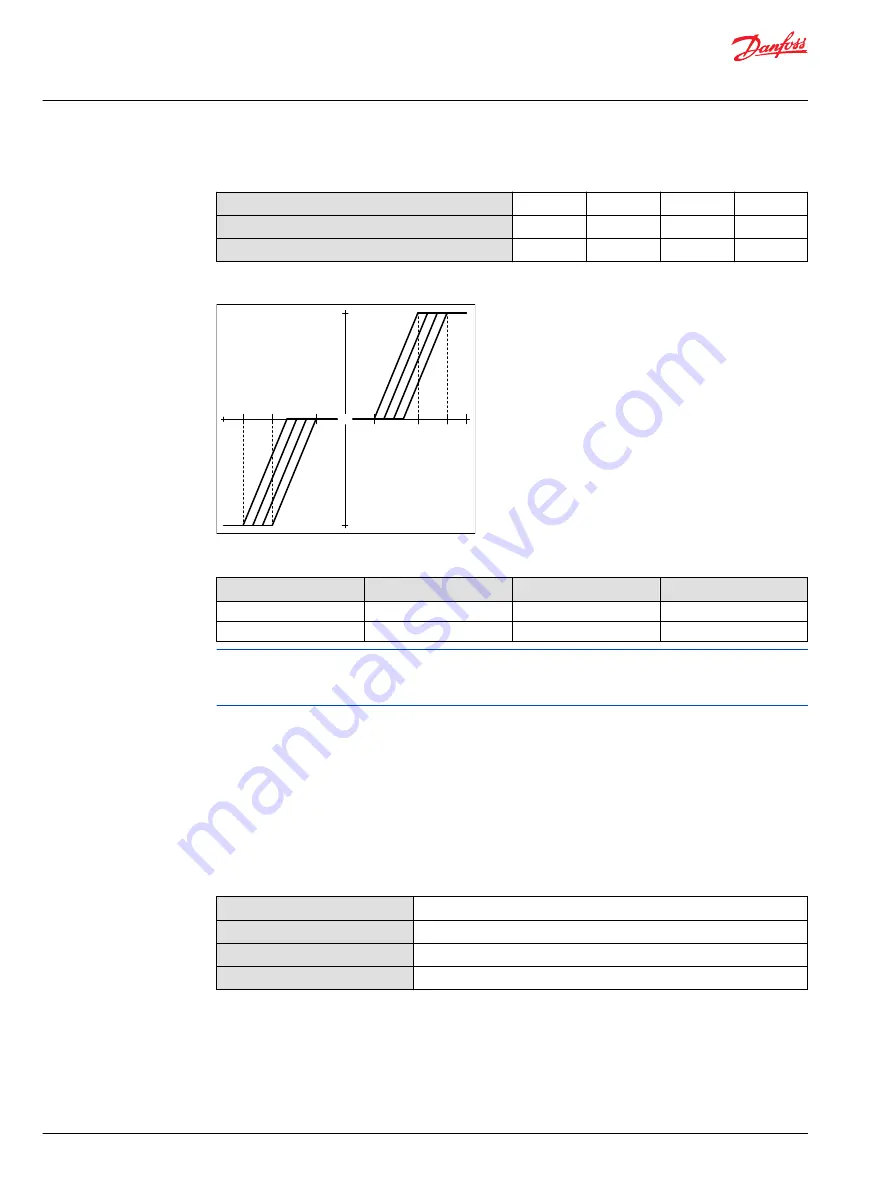
Pump Flow Direction with NFPH control (continued)
Port A flow
Out
In
In
Out
Port B flow
In
Out
Out
In
High servo gauge port
M4
M5
M4
M5
NFPH pump displacement to Input signal
"0"
Signal Current
mA(DC)
a
b
c
a
b
c
Displac
emen
t
100 %
100 %
NFPE control
∆
p = 300 bar
∆
p = 300 bar
∆
p = 0 bar
∆
p = 0 bar
P003 187E
NFPH input signal pressure (bar)
Frame size
a
b
c
28/32
5.5
13.7
17
38/45
5
12.75
16
The values provided in the table above are approximations at 1800 RPM and system delta pressures as
indicated in the graph provided. The values are dependent on input speed and delta pressure operating
conditions.
Control Response
MP1 controls are available with optional control passage orifices to assist in matching the rate of
swashplate response to the application requirements (e.g. in the event of electrical failure). The time
required for the pump output flow to change from zero to full flow (acceleration) or full flow to zero
(deceleration) is a net function of spool porting, orifices, and charge pressure. A swashplate response
table is available for each frame indicating available swashplate response times. Testing should be
conducted to verify the proper orifice selection for the desired response.
Typical response times at the following conditions:
∆p
250 bar [3626 psi]
Viscosity and temperature
30 mm
2
/s [141 SUS] and 50°C [122 °F]
Charge pressure
24 bar [348 psi]
Speed
1800 min
-1
(rpm)
Service Manual
MP1
Operation
30 |
©
Danfoss | April 2019
AX00000244en-000201


