Calibration of the sensor output within the software is mandatory. Vehicle neutral thresholds in the
software (±0.5°) are vehicle dependent and must consider different conditions, example: system
temperature, system pressure and/or shaft speed.
For safety function: If the sensor fails (invalid signal <10% or >90% of supply voltage), it must be sure
that the ECU will go into a diagnostic mode and shift into limited mode in order for the driver to take the
full control or the mechanical breaks should be activated.
Strong magnetic fields in the proximity of the sensor can influence the sensor signal and must be
avoided.
Swash Plate Angle Sensor Connector
Connector DEUTSCH, 4-pin
2
3
4
1
Pin assignment:
1. Ground (GND)
2. Not connected
3. Output signal 1 (SIG 1)
4. Supply (V+)
Connector order numbers
Description
Quantity
Order number
Mating connector DTM06-4S-E004
1
11105824
Wedge lock WM-4S
1
not available
Socket contact 0462-201-2031
3
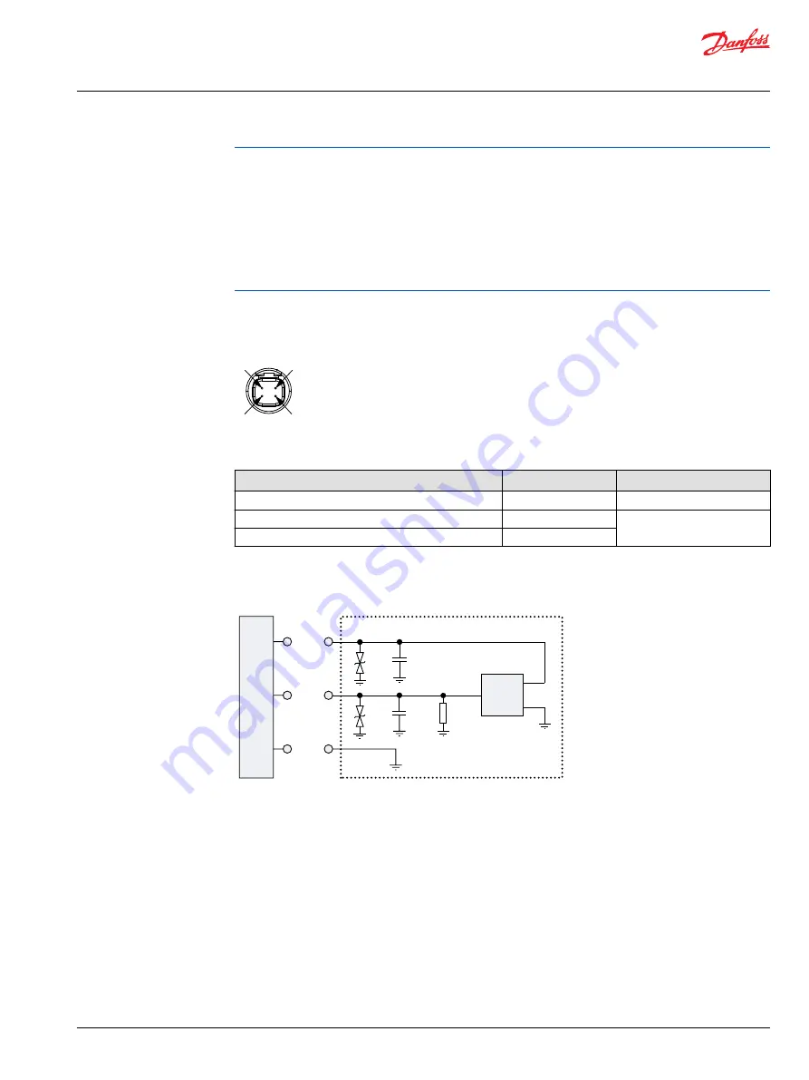
Interface with ECU (EDC)
Interface with ECU diagram
ECU
Supply
Signal
GND
GND
OUT
VCC
100 nF
20 kΩ
100 nF
Manual displacement control
MDC principle
An MDC is a Manual proportional Displacement Control (MDC). The MDC consists of a handle on top of a
rotary input shaft. The shaft provides an eccentric connection to a feedback link. This link is connected on
its one end with a porting spool. On its other end the link is connected the pumps swashplate.
This design provides a travel feedback without spring. When turning the shaft the spool moves thus
providing hydraulic pressure to either side of a double acting servo piston of the pump.
Differential pressure across the servo piston rotates the swash plate, changing the pump’s displacement.
Simultaneously the swashplate movement is fed back to the control spool providing proportionality
between shaft rotation on the control and swashplate rotation.
Service Manual
MP1
Operation
©
Danfoss | April 2019
AX00000244en-000201 | 19


