


© Danfoss | DCS (vt) | 2020.10
4 | AN320819413085en-000401
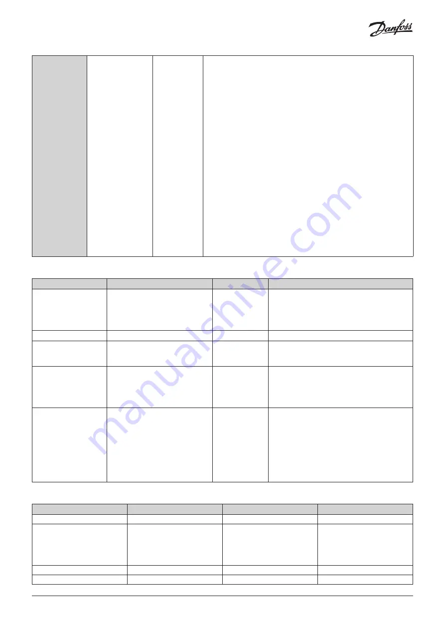
Digital
output
Relay
20 (MCX20B2)
15 (MCX15B2)
Concerning the insulation distance there are three groups of relays:
• group 1: relays 1 to 8
• group 2: relays 9 to 13
• group 3: relays 14 to 20
Insulation between relays of the same group: functional
Insulation between relays of different groups: reinforced
Insulation between relays and the extra-low voltage parts: reinforced
Total current load limit: 65 A
C1-NO1 to C13-NO13, C16-NO16 to C20-NO20 on MCX20B2
C1-NO1 to C13-NO13 on MCX15B2
Normally open contact relays 5 A
Characteristics of each relay:
– 5 A 250 V AC for resistive loads - 100,000 cycles
– 3 A 250 V AC for inductive loads - 100,000 cycles with cos(phi) = 0.4
– UL: 3 A resistive, 250 V AC, 100,000 cycles; 1/8 hp, 125/250 V AC,
30,000 cycles; C300 pilot duty, 125/250 V AC, 30,000 cycles
C14-NO14-NC14, C15-NO15-NC15
Changeover contact relays 16 A
Characteristics of each relay:
– 7 A 250 V AC for resistive loads - 100,000 cycles
– 3.5 A 250 V AC for inductive loads - 230,000 cycles with cos(phi) = 0.4
– UL: NO contact: 6 A resistive, 240 V AC, 30.000 cycles; 1/2 hp, 240
V AC, 30.000 cycles; 470 VA pilot duty, 240 V AC, 30.000 cycles. NC
contact: 6 A resistive, 6.000 cycles
C3 NO3 to C6 NO6
Optionally they can be solid state relays
Characteristics of each relay:
15-280 Vrms, 0.5 A
UL: 0.5 A resistive, 240 V AC, 30,000 cycles
Interface
Use
Connector label
Technical data
CANbus
Fieldbus for connection to user
interfaces, MCX controllers, service
tools etc.
CAN
CAN-RJ
Physical layer according to ISO 11898-2 High
Speed CAN bus
Frame format according to CAN 2.0B specification
Transceiver not isolated (power supply has
reinforced isolation)
USB device
Prepared for future use
USB-DEV
Plug: Type Mini B
USB host
For connection to Flash drive
for application software update,
datalogging and service
USB-H
Plug: Type A
RS485-1
RS485-2 (MCX20B2 only)
Communication bus to BMS (e.g.
Modbus slave), service tools, smart
devices (e.g. Modbus master)
RS485-1 can be polarized as master
from the application
RS485-1
RS485-2
Physical layer according to EIA 485 Ref3
Provide 500 V peak transient galvanic isolation
Ethernet
For web server functionality,
integration (e.g. Modbus TCP)
NOTICE! Do not route cable outside
of buildings.
Connect only to IT equipment
compliant with EN 60950 or EN
62368 (Information technology
equipment. Safety. General
requirements)
ETHERNET
Interface type: 10 BASE-T and 100 BASE-TX, IEEE
802.3.
MDI-X (Automatic medium-dependent interface
crossover)
Communication interface
Wire lengths
Interface
Max wire length (m)
Max. baudrate (bps)
Min. wire size
Ethernet
100
10/100 M
CANbus
1000
500
250
80
30
50 K
125 K
250 K
500 K
1 M
AWG18
AWG22
AWG24
AWG26
AWG26
RS485
1000
125 K
AWG22
Signal wiring
30