background image

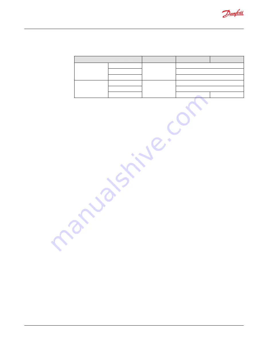
LDT Fluid Specification

Features

Units

LDT21

LDT24/32

Viscosity

Minimum

mm

2

/sec. [ SUS]

7 [49]

Recommended range

12-60 [66-280]

Maximum

1600 [7500]

Temperature

Minimum

°C [°F]

-40 [-40]

Rated

82 [180]

Maximum

95 [203]

104 [220]

Service Manual

LDT 21/24/32 Closed Circuit Axial Piston Transmission

Technical Specifications


©

 Danfoss | June 2022

AX417167456877en-000101 | 15

Содержание LDT 21

Страница 1: ...Service Manual LDT 21 24 32 Closed Circuit Axial Piston Transmission www danfoss com...

Страница 2: ...Revision history Table of revisions Date Changed Rev June 2022 First edition 0101 Service Manual LDT 21 24 32 Closed Circuit Axial Piston Transmission 2 Danfoss June 2022 AX417167456877en 000101...

Страница 3: ...irements 11 Operating Parameters Overview 12 Input Output Speed 12 System Pressure 12 Input Power 12 Charge Pressure 12 Case pressure 13 Viscosity 13 Temperature 13 Technical Specifications General Sp...

Страница 4: ...er charge check HPRV operation 21 Minor Repair Shaft Seals 22 Removal 22 Inspection 22 Assembly 22 Charge Check HPRV 23 Removal 23 Inspection 23 Reassembly 23 Torque Chart LDT24 Plug Size and Torque C...

Страница 5: ...be under high pressure and or hot Inspect the outside of the HST and fittings for damage Cap hoses and plug ports after removal to prevent contamination Keep it clean Cleanliness is a primary means of...

Страница 6: ...is fluid may also be hot enough to cause burns Use caution when dealing with hydraulic fluid under pressure Relieve pressure in the system before removing hoses fittings gauges or components Never use...

Страница 7: ...hp Compact design U style layout in one housing with Z shaft configuration Requires external charge flow LDT21 24 feature 85mm between pump and motor shaft centers identical to BDU21 and LDU20 LDT32 s...

Страница 8: ...atic MB1 E M3 L3 MB2 MA2 L2 L1 MA1 LDT32 hydraulic schematic MB1 E L3 MB2 MA2 L2 L1 MA1 Service Manual LDT 21 24 32 Closed Circuit Axial Piston Transmission General Description 8 Danfoss June 2022 AX4...

Страница 9: ...d help provide a larger margin of safety for vehicle movement in neutral and provide easier adjustment of the vehicle linkage for machine neutral The orifice connects the working loop which is a main...

Страница 10: ...d level For external charge flow the CPRV is set according to below table The charge pressure relief valve setting is specified on the model code of the unit Charge Pressure Relief Valve settings for...

Страница 11: ...Control Moments Deadband LDT21 LDT24 LDT32 Stroke decreasing moment at max working system pressure full stroke 2500 RPM input speed 30 mm2 sec N m lbf in 8 6 76 20 177 20 177 Minimum return spring for...

Страница 12: ...em Pressure System pressure is the differential pressure between system ports A B It is the dominant operating variable affecting hydraulic unit life High system pressure which results from high load...

Страница 13: ...ble Temperature 1 Maintain fluid temperature within the limits shown in the Technical Specification section Minimum temperature relates to the physical properties of the component materials Cold oil m...

Страница 14: ...30 9 21 0 46 3 Oil volume Case only liter US gal 0 9 0 24 1 1 0 29 1 4 0 38 With passage 1 0 0 26 1 2 0 31 1 5 0 41 Installation See Rotation Clockwise Clockwise Clockwise Ports ISO 11926 1 See Input...

Страница 15: ...mm2 sec SUS 7 49 Recommended range 12 60 66 280 Maximum 1600 7500 Temperature Minimum C F 40 40 Rated 82 180 Maximum 95 203 104 220 Service Manual LDT 21 24 32 Closed Circuit Axial Piston Transmissio...

Страница 16: ...of operation Fluid and Filter Change Interval Reservoir Type Max Oil Change Interval Sealed 2000 Hours Breather 500 Hours C Caution High temperatures and pressures accelerate fluid aging This may requ...

Страница 17: ...Port Identifier Port Size Wrench Size Reading Gauge Size bar psi L1 L2 16 UNF 5 16 Internal Hex Case Drain 10 100 MA1 MA2 MB1 MB2 9 16 18 UNF Internal Hex System Pressure 500 7250 M3 9 16 18 UNF Inte...

Страница 18: ...ur if the fluid supply runs out Ensure reservoir remains full of fluid during start up Air entrapment in oil under high pressure may damage hydraulic components Check carefully for inlet line leaks Do...

Страница 19: ...eservoir Insufficient hydraulic fluid to supply system loop Fill reservoir to proper level Charge pressure with pump in neutral Low charge pressure insufficient to recharge system loop Measure charge...

Страница 20: ...in system produces sluggish system response Fill tank to proper level Cycle system slowly for several minutes to remove air from system Charge inlet vacuum Inlet vacuum is too high resulting in reduce...

Страница 21: ...of system contamination such as oil discoloration foam in the oil sludge or small metal particles 4 Remove the transmission C Caution Be careful not to damage solenoids and electrical connections when...

Страница 22: ...2 Using a seal installation tool start the seal into the housing bore Hand press the seal the rest of the way into the housing bore Ensure the seal clears the retaining ring groove in the housing Remo...

Страница 23: ...Reassembly 1 Lubricate and install new O rings QM310 QN310 on valve seat plug M300 N300 2 Verify that the conical springs M200 N200 are properly retained on the check relief valves M100 N100 Install t...

Страница 24: ...0 20 UNF 17mm External Hex 27 1 16 6 G020 16 UNF 5 16 Internal Hex 39 2 58 G030 16 UNF 5 16 Internal Hex 39 2 58 H120 H130 16 UNF 5 16 Internal Hex 39 2 58 Service Manual LDT 21 24 32 Closed Circuit A...

Страница 25: ...anfoss Power Solutions US Company 2800 East 13th Street Ames IA 50010 USA Phone 1 515 239 6000 Danfoss Power Solutions Trading Shanghai Co Ltd Building 22 No 1000 Jin Hai Rd Jin Qiao Pudong New Distri...

Отзывы: