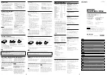
MG.03.F5.02 - VLT is a registered Danfoss trademark
02/00
The control cables must be screened cables.
X101: Terminal block for analog/digital control signals
Terminal
Function
Example
No.
1
Analog input (0-20 mA)
Feedback
signal
2
Analog (0-10 V)/digital input 2
Speed
reference
3
Digital input (or pulse) 3
Reset
4
Digital input (or precise stop) 4
Start
5
Digital input (other) 5
Jog (fixed
speed)
6
24 V DC supply for digital inputs (max. 50 mA)
7
10 V DC supply for potentiometer (max. 15 mA)
8
0 V for terminals 1-7 and 9
9
Analog (0-20 mA)/digital output
Fault
indication
X100: Terminal block for data communication
Terminal
Function
No.
1
P RS 485
for connection to
2
N RS 485
bus or PC
3
5 V DC
Supply for RS 485 bus
4
0 V DC
T
T
T
T
Table B
able B
able B
able B
able B
Reset (pushbutton)
Start
Jog
Speed reference
Terminals
1: Analogue input
2: Analogue input
3: Digital input
4: Digital input
5: Digital input
6: 24 V DC supply
7: 10 V DC supply
8: 0 V
9: Output
-
Reset
to be closed short time for
resetting fault trips
-
Start
to be closed for changing
to
run mode
-
Jog
will run at fixed speed
while closed (10 Hz)
-
Speed reference
(0-10 V)
determines speed while in
run mode
Fig. 1
Fig. 1
Fig. 1
Fig. 1
Fig. 1
Factory setting
T
T
T
T
Table A
able A
able A
able A
able A
Fig. 2
Fig. 2
Fig. 2
Fig. 2
Fig. 2
175R0129
➊
Mechanical installation
Mechanical installation
Mechanical installation
Mechanical installation
Mechanical installation
Install the FC motor with adequate access for routine
maintenance. Adequate space, particularly at the fan
inlet (50 mm), is necessary to facilitate airflow.
Where several FC motors are installed in close
proximity, care must be taken to ensure that there is
no recirculation of exhausted warm air.
N B !
N B !
N B !
N B !
N B !
Ambient temperature
To avoid the FC part getting overheated, the
ambient temperature is not to exceed 40 °C
and the 24-hour average temperature is not to exceed
35 °C. If the ambient temperature is in the range of
40 °C - 55 °C, a reduction of the service life of the FC
part is to be expected. For further information, please
see the section on derating in the Design Guide.
N B !
N B !
N B !
N B !
N B !
Bearings
Ball and roller bearings are despatched from
the works fully charged with grease. Shielded
bearings have sufficient grease for an operating life of
at least two years in normal ambient temperatures,
providing there is little or no leakage.
Tapping of fitments onto the motor shaft,
with a hammer or mallet, causes bearing
damage. This results in increased bearing
noise and a significant reduction in bearing life.
VL
VL
VL
VL
VLT
T
T
T
T
®
®
®
®
®
DriveMotor FCM 300 Quick Setup
DriveMotor FCM 300 Quick Setup
DriveMotor FCM 300 Quick Setup
DriveMotor FCM 300 Quick Setup
DriveMotor FCM 300 Quick Setup
➋
Electrical connections
Electrical connections
Electrical connections
Electrical connections
Electrical connections
Remove the inverter box cover, which is held by four
screws, to obtain access to the terminals.
Remove the detachable terminal plugs from the
terminal blocks X100 and X101 to obtain access to
the mains terminals.
Lift only the corner of the black plastic cover by the
cable entries to expose the mains terminals L
1
, L
2
and
L
3
(see fig. 2).
N B !
N B !
N B !
N B !
N B !
Do not lift or remove the entire plastic
cover. The voltage on the FC motor is
dangerous and may lead to material
damage, serious injury or it may be fatal.
N B !
N B !
N B !
N B !
N B !
Mains terminals L
1,
L
2
and L
3
:
Make sure that your mains supply
corresponds to the voltage required by the FC
motor (see inverter label), TT and NT mains .
Connect the three mains phases to terminals L
1,
L
2
and
L
3
and the earth to the separate terminal provided.
T
T
T
T
T ightening T
ightening T
ightening T
ightening T
ightening Tor
or
or
or
orques
ques
ques
ques
ques
L1, L2, L3
FCM 305-340
0,5-0,6 Nm
L1, L2, L3
FCM 355-375
1,2-1,5 Nm
Earth
ground FCM 305-375
3,4 Nm
Fixed wires:
Rated temperature for fixed wires min. 60
°
C or
140
°
F. Use copper conduction only.
N
N
N
N
N B !
B !
B !
B !
B !
You cannot change the rotation direction of the
motor by shifting around the phases. The
direction of rotation is clockwise by default.
Another direction of rotation can be programmed, see
the Design Guide.
Prefuses Max.
Prefuses Max.
Prefuses Max.
Prefuses Max.
Prefuses Max.
UL
1)
FCM 305-322
10A
FCM 330-340
15A
FCM 355-375
25A
IEC
1)
FCM 305-375
25A
1)
Type gG prefuses must be used. If you want to maintain
UL/cUL you must use prefuses of the type Bussmann
KTS-R 500 V or Ferraz Shawmut, type ATMR (max. 30A). The
fuses must be placed for protection in a circuit that is capable of
supplying a maximum of 100,000 amps RMS (symmetrical), 500
V maximum.
Contr
Contr
Contr
Contr
Control terminals
ol terminals
ol terminals
ol terminals
ol terminals
For information on terminal blocks X100 and X101, please
see table A and B.
RS 485 switch
RS 485 switch
RS 485 switch
RS 485 switch
RS 485 switch
For terminating an RS 485 interface serial communication,
the bus must be terminated by a resistor network at both
ends. This is provided by setting both switches to ON.
LEDs
LEDs
LEDs
LEDs
LEDs
The FC motor has five LEDs which indicate the status of
the FC motor:
LED 300 (red):
Fault trip
LED 301 (yellow):
Warning
LED 302 (green):
Power on
LED 303-304 (green):
Communication
EMC-corr
EMC-corr
EMC-corr
EMC-corr
EMC-correct installation
ect installation
ect installation
ect installation
ect installation
The control cables must be screened cables to ensure
EMC-correct electrical installation.
Connect the screen to earth at both ends.
Avoid installation with twisted screen ends (pigtails), since
this ruins the screening effect at high frequencies. Use
cable clamps instead.
➌
Start the FC motor
Start the FC motor
Start the FC motor
Start the FC motor
Start the FC motor
Connect mains. LED 302 (green) lights up to indicate
that the power is on. In Profibus versions, LED 303
will flash. For further information on Profibus, please
see the Profibus manual.
Connect terminal 4 and 6 to the start button (see fig.
1).
Connect terminal 2, 7 and 8 to the potentiometer
(see fig. 1).
The voltage on the FC motor is
dangerous when the motor is connected
to mains. Incorrect installation of the FC
motor may lead to material damage or
serious injury or it may be fatal.
➍
Mount the inverter box cover.
Fastening torque: 2.2 - 2.4 Nm
Use the start button to start the FC motor and adjust the
speed by means of the potentiometer.
Motors type B14 & B34 mounting
1) Max length of the fixing bolts / screws
penetrating the B14 flange:
FCM 305-307 (frame 80) =
11.0 mm
FCM 311-315 (frame 90) =
11.5 mm
FCM 322-330 (frame 100) =
15.0 mm
FCM 340 (frame 112) =
15.5 mm
FCM 355-375 (frame 132) =
17.0 mm
2) The following precautions must be taken:
a) A non-setting jointing and sealing
compound must be used to seal the bolt /
screw threads in the motor flange.
b) A soft copper washer must be inserted
underneath the bolt / screw head.
c) The joint face between the motor flange
and the mounting must be sealed using
non-setting jointing and sealing compound.
For B34 types where it is only foot mounted, the flange
is not used. Then the bolts should be fitted in
accordance with parts a) & b) of item 2 to maintain the
IP55.