background image

Hoisting, aiming and securing the array

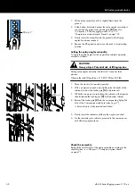
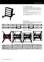
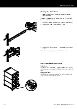
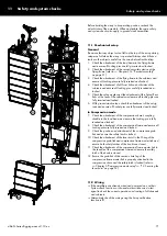
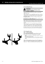
12.2.2  Vertical aiming

In connection with the Z5711 ArraySight sender unit (laser

inclinometer), the vertical aiming of the array can be sufficiently

and easily adjusted.

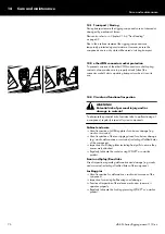
 CAUTION!

Potential risk of personal injury.

The high brightness laser of the d&b ArraySight sender unit

requires additional safety considerations.
1. Take precautions to prevent anyone from looking directly

into the laser beam.

2. Wear appropriate eye protection.
3. When making adjustments to the array with motor hoists,

watch the hoist - 

not the meter unit!

4. Check the measurement only when you are satisfied that the

hoist has finished moving safely.

5. However, the chain hoist motors must raise slowly and

evenly.

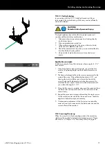
Application example
To take an example: ArrayCalc indicates a frame angle of –3.6°

from vertical.
1. Using ArraySight to measure this angle, you raise the first

array to its operating height and then check the meter unit

screen.

2. The figures displayed settle as the meter compensates for the

swing of the array. If the settled display shows +0.5°, you

then use the hoists to lift the rear or lower the front of the

array. Make small adjustments and allow the meter unit to

calculate the new angle. Continue to make adjustments until

you achieve the angle of –3.6°.

3. Once the first array is complete, disconnect the meter unit from

the first sender unit and reconnect it to the sender unit of the

second array.

4. Repeat the procedure, starting with resetting the angle to zero

for the second sender unit. Raise the second array, check the

angle and adjust the angle as necessary.

5. If subsequent re-adjustment of the first array is required the

meter unit can be re-connected to the first sender unit and the

correct offset will be recalled.

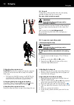
12.3  Securing the array
When the array is in its final operating position, the secondary

safety must be applied to its dedicated suspension point. Please

also refer to 

Þ

 Chapter 3.14 "Secondary safety" on page 31 .


d&b SL-Series Rigging manual 1.10 en

73

Содержание SL Series

Страница 1: ...SLSL Series Rigging manual 1 10 en ...

Страница 2: ...e d b website for the latest version of this document When reselling this product hand over this document to the new owner If you supply d b products please draw the attention of your customers to this document Enclose the relevant documents with the systems If you require additional documents for this purpose you can order them from d b d b audiotechnik GmbH Co KG Eugen Adolff Str 134 D 71522 Bac...

Страница 3: ... SUB SL GSUB 39 3 16 3 E7804 Touring cart KSL SUB 40 3 16 4 Truck loading 42 4 SL Series array assemblies overview 43 5 SL Series array assembly Preassembly 44 5 1 Setup preparation 44 5 1 1 Suspending the load beam 44 5 1 2 Attaching the load beam to the flying frame 45 5 1 3 Connecting the d b ArraySight sender unit 46 6 Compression mode setup 47 7 Tension mode setup 54 8 SUB columns 58 8 1 Limi...

Страница 4: ...s provided by the Help system of the software To access the help system press F1 or select the help button from the ArrayCalc toolbar This will launch the Help which provides an overview of the program as well as a search function and direct access to the related topics In addition ArrayCalc will provide you with typical array configurations within the permitted load limits and will help you get f...

Страница 5: ...tem weight of 1500 kg 3307 lb SWL including all rigging components This allows the suspension of a maximum of 24 x KSL TOP cabinets or a SUB column consisting of a maximum of 16 x KSL SUB cabinets The rigging components allow arrays of up to 10 x KSL TOP cabinets with a total system weight of 685 kg 1510 lb to be flown in any vertical splay angle configuration between the cabinets For any other ar...

Страница 6: ...tions given on the respective instruction labels of the rigging components such as load beams flying and compression frames touring carts and loudspeaker cabinets In connection with the d b Z5711 ArraySight sender unit laser inclinometer take precautions to prevent anyone from looking directly into the laser beam and wear appropriate eye protection Be aware that any object or tool left on the top ...

Страница 7: ...ng modes while the 9 hole of the Tension mode hole grid is used to park the Splay link Þ Locking pin conventions Pin 1 Pin 2 Tension mode In Tension mode pin 1 is used to preset the splay angle of a certain cabinet on the top hole grid of the cabinet itself During hoisting the Splay link of the upper cabinet will engage and safety pin 2 is inserted in the hole directly below Compression mode In Co...

Страница 8: ...e grid Þ First cabinet to frame For both Tension and Compression modes the Splay link of the flying frame is always engaged in the 0 hole of the top hole grid of the first cabinet using pin 1 and safety pin 2 Overview charts The following charts provide an overview of the rigging mode principles of the GSL system at one glance The same principles also apply to the KSL system d b SL Series Rigging ...

Страница 9: ...SL Series rigging modes 2 in 1 Tension mode principle d b SL Series Rigging manual 1 10 en 9 ...

Страница 10: ...SL Series rigging modes 2 in 1 Compression mode principle Preset d b SL Series Rigging manual 1 10 en 10 ...

Страница 11: ...SL Series rigging modes 2 in 1 Compression mode principle Curved Compressed d b SL Series Rigging manual 1 10 en 11 ...

Страница 12: ...propriate shielded CAT5e 1 1 cable K6006 200 00 30 m 100 ft is also enclosed 2 Z5702 GSL Load beam 29 kg 64 lb 3 Z5705 Safety chain 4 t 7 kg 15 4 lb 4 Z5713 SL Cable pick 1 5 kg 3 3 lb Z5721 KSL Flying frame set Set Including Z5721 KSL Flying frame set 60 kg 132 3 lb 1 Z5722 KSL Flying frame 30 3 kg 66 8 lb equipped with a Z5711 ArraySight sender unit 1a An appropriate shielded CAT5e 1 1 cable K60...

Страница 13: ...5 B2447 074 Compression frame master link 3 5 kg 7 7 lb 6 B2447 075 Chain bag 0 75 kg 1 65 lb Z5724 KSL Compression set Set Including Z5724 KSL Compression set 41 kg 90 4 lb 1b Z5725 KSL Compression frame 16 kg 35 3 lb 2 Z5709 SL Compression chain 2 5 t 12 1 kg 26 7 lb 3 B2447 073 Compression grab link 1 4 kg 3 1 lb 4 B2447 072 Lever hoist 7 5 kg 16 5 lb 5 B2447 074 Compression frame master link 3...

Страница 14: ... SL Series flying frames Please verify the shipment for completeness and proper condition of the items The SL Series flying frames are equipped and supplied with the following rigging components d b SL Series Rigging manual 1 10 en 14 ...

Страница 15: ...es are fitted with two safety points each equipped with a 4 75 t shackle to attach a secondary safety device using the enclosed Safety chain refer to Þ Chapter 3 14 Secondary safety on page 31 6 etherCON connector socket In connection with the d b Z5711 ArraySight sender unit the etherCON connector socket acts as a feed through to allow for easy connection of the sender unit 7 Rear link adapter To...

Страница 16: ...SL Series rigging components 3 2 1 Dimensional drawings Z5701 GSL Flying frame dimensions in mm inch Z5722 KSL Flying frame dimensions in mm inch d b SL Series Rigging manual 1 10 en 16 ...

Страница 17: ...ting of GSL 33 KSL 26 25 mm 1 holes 1b Z5723 KSL Load beam 2 Two 4 75 t shackles are provided to allow direct connection to the chain hoist motor hook or to attach the Z5706 Hoist connector chain and or the Z5707 SL Aiming plate Instruction labels providing vital safety and rigging instructions 3 3 1 Load beam operating modes The SL Series load beams allow for two operating modes STANDARD MODE In ...

Страница 18: ...hole for the attachment of the Z5713 SL Cable pick or a standard 3 25 t shackle 6 Hole position for the attachment of the Z5709 SL Compression chain Pos Description 3a b Hole positions for the two rigging modes Hole pair 3a for STANDARD MODE Hole pair 3b for FRONT EXTENSION 4a b Hole position for the cable pick providing a 21 mm 0 8 hole for the attachment of the Z5713 SL Cable pick or a standard ...

Страница 19: ...de steel following the principles of truss construction to achieve the lowest possible dead weight of GSL 18 6 kg 41 lb KSL 16 kg 35 3 lb including all rigging components They are attached to the bottom of the last cabinet of the array 1b Z5725 KSL Compression frame 2 Locking pins front Two Locking pins Type C 10 x 35 mm are provided to attach the compression frame to the front rigging strands of ...

Страница 20: ...SL Series rigging components 3 4 1 Dimensional drawings Z5703 GSL Compression frame dimensions in mm inch Z5725 KSL Compression frame dimensions in mm inch d b SL Series Rigging manual 1 10 en 20 ...

Страница 21: ...wing rigging components Pos Component Description 1 Z5747 KSL SUB Adapter frame The KSL SUB Adapter frame is constructed from high grade steel following the principles of truss construction to achieve the lowest possible dead weight of 38 kg 84 lb including all rigging components 2 Locking pins front Two fixed Front links including corresponding Locking pins 2a type C 10 x 35 mm are provided to at...

Страница 22: ...SL Series rigging components 3 5 1 Dimensional drawing Z5747 KSL SUB Adapter frame dimensions in mm inch d b SL Series Rigging manual 1 10 en 22 ...

Страница 23: ...necting link and a grab hook with safety latch 4 B2447 072 Lever hoist 7 5 kg 16 5 lb For SL Series line arrays in Compression mode the lever hoist is used to manually curve the array 5 B2447 074 Compression frame master link 3 5 kg 7 7 lb For SL Series line arrays in Compression mode the compression frame master link is used to link the B2447 072 Lever hoist to the rear pickpoint of the GSL or KS...

Страница 24: ...knob 2 Lever mode selector N Neutral UP Lifting clockwise DN Lowering counter clockwise 3 Lever 4 Load indicator Green Safe load Þ Continue operation Red Overload Þ Lever kinks Þ Stop operation 3 7 1 Operation Free chaining operation WARNING Potential risk of personal injury and or damage to material Do NOT operate the hoist in free chaining mode under load In free chaining mode the brake is relea...

Страница 25: ...lever stops the mechanical brake is tightened again and supports the load instantly Load indicator The load indicator is designed as an overload detecting device In connection with d b SL Series line arrays in Compression mode this device indicates that the maximum permitted compression force has been achieved NOTICE To provide correct detection of the compression force applied operate the hoist b...

Страница 26: ... rating 4 t Weight 7 kg 15 4 lb 3 9 Z5706 Hoist connector chain 4 t The Z5706 Hoist connector chain is used to connect the lifting motor s to the SL Series load beams using the 4 75 t shackles of the corresponding load beam Its length of 530 mm 21 allows enough space for the hang of most 2 t motor chain containers and avoids any impact on the vertical balance of the array Specification Lifting cha...

Страница 27: ...al aiming of an entire array using two motor hoists With a chain hoist distance of minimum 0 6 m 2 ft preferably approx 1 m 3 ft the SL Aiming plate provides a horizontal angle range of 15 first and last pick holes of the load beam used 2 Two 4 75 t shackles are provided to allow direct connection to the motor hoist hooks or to attach the Z5706 Hoist connector chain 3 Load hook for attachment to t...

Страница 28: ...ion reasons such as altering the position of the Frame s Rear link or exchanging a shackle it may be necessary to temporarily remove the ring cotter and reattach it afterwards Note Please also refer to Þ Chapter 14 Care and maintenance Þ 14 3 Visual and functional inspection Þ Ring cotters on page 77 For this purpose proceed as follows 1 Unlock Unlock the ring cotter by pushing up the front wire l...

Страница 29: ...16 x 55 mm Used for the flying frames and the coupling shackle of the SL Compression chain and the SL Cable pick B Locking pin 12 x 45 mm for GSL TOP SL SUB cabinets Locking pin 10 x 45 mm for KSL TOP KSL SUB cabinets Used for the cabinets Splay Rear links the compression frames pickpoints the touring carts Splay Rear link slot s C Locking pin 10 x 35 mm Used for the Front links of the loudspeaker...

Страница 30: ...he array is fully set up hoisted and secured as intended Attachment 1 Choose the appropriate hole position on the load beam according to the ArrayCalc calculation and attach the shackle correspondingly 2 Attach the hoist connector chain or motor hook to the shackle of the load beam respectively 3 13 2 Dual pickpoint operation With Dual pickpoint operation the vertical aiming of the array is set by...

Страница 31: ...safety points 5 and secured against loosening using a locked ring cotter C as shown in the graphic opposite 2 Attach the safety chain set and ensure the chains are not twisted and the hooks H are in the right direction as shown in the graphic opposite 3 15 Cabinet rigging mechanism The cabinets are mechanically connected to the flying frame and subsequent loudspeakers using the Front links attache...

Страница 32: ...inets Þ Fig 2 3 SUB to SUB with 2 splay free between the cabinets Þ Fig 3 4 SUB to SUB with 2 splay blocked between the cabinets Þ Fig 4 This setting is used to prevent the cabinets from folding up Fig 1 SUB to Frame Fig 2 SUB to SUB 0 splay Fig 3 SUB to SUB 2 splay free Fig 4 SUB to SUB 2 splay blocked 3 15 2 Splay Rear link mechanism Release the respective Locking pin s and fold out the Splay Re...

Страница 33: ...equipped and supplied with the following rigging components Please verify the shipment for completeness and proper condition of the items 3 16 1 GSL KSL Touring carts 3 16 1 1 E7490 GSL Touring cart Pos Component Description 1 E7490 Touring cart 4 x GSL8 GSL12 Dead weight 58 kg 128 lb Total weight 378 kg 833 lb 4 x TOP cabinets incl cover Total weight 453 kg 1000 lb incl flying frame and load beam...

Страница 34: ... as brake wheels cross mounted Touring cart instruction label providing vital safety and rigging instructions 3 16 1 3 E7495 KSL Touring cart Tension Pos Component Description 1 E7495 Touring cart 4 x KSL8 KSL12 Dead weight 55 kg 121 lb Total weight 293 kg 646 lb 4 x TOP cabinets incl cover Total weight 344 kg 758 lb incl flying frame and load beam Dimensions H x W x D cm 175 x 110 x 78 H x W x D ...

Страница 35: ...lifting devices KSL cabinets can be loaded without the need of additional lifting devices Once the lifting device is attached proceed as follows Storage modes With respect to the SL Series rigging modes Compression or Tension mode GSL and KSL cabinets can be stored in the cart in a prepared condition for operation in one of the two modes Manually loading for Compression mode The following procedur...

Страница 36: ...binet and reinsert its Locking pins on both sides 10 Raise the back of the cabinet and release all Locking pins 11 Fold out the Splay link and insert Locking pin 3 to the Tension mode hole at the bottom of the rigging strand Þ 12 At the bottom cabinet reinsert Locking pin 1 to the 0 hole Þ at the top of the rigging strand 13 Lower the cabinet and insert the Splay link into the rear rigging strand ...

Страница 37: ...rigging strand Þ 6 Insert the Splay link into the Splay link slot 7 Lift the back of the cabinet until the Splay link has engaged and reinsert the bottom Locking pin to fix the link in place 8 Finally extend the Front links of the first cabinet to attach the next cabinet 9 Attach the next cabinet to the previously extended Front links of the first cabinet and reinsert its Locking pins on both side...

Страница 38: ...igging strand of the cabinet 5 Raise the back of the flying frame until the Rear link has engaged 6 Reinsert the Locking pin 2 Safety pin Storing and fixing the load beam The GSL Touring cart provides a storage tray for the Z5702 GSL Load beam Underneath this storage tray additional slotted holes are provided on each side to fix the load beam using an appropriate ratchet strap In KSL Touring carts...

Страница 39: ...ft to 80 cm 2 5 ft The wheels are fixed using M8 x 20 mm grade 8 8 locking screws and self locking nuts M8 To alter the position proceed as follows Tools required Torque wrench size 13 1 2 AF 1 Slacken and undo the four self locking nuts and remove the locking screws 2 Move the wheel to its new position 3 Redo all screws and nuts and tighten the screws to a torque of 24 N m Loading the cart As for...

Страница 40: ...rt 3 x KSL SUB Dead weight 45 kg 100 lb Total weight 291 kg 642 lb 3 x SUB cabinet Total weight 380 kg 840 lb incl flying frame load beam and adapter frame Dimensions H x W x D cm 185 x 120 x 110 H x W x D inch 73 x 47 5 x 43 5 2 Eight guide lugs at the front left right and rear of the cart 3a 3b Dedicated supports at the front left and right 3a and corresponding Locking pins 3b Type C 10 x 35 mm ...

Страница 41: ... same manner Adapter frame storage tray The cart also allows the storage of a SUB cabinet assembly with the KSL SUB Adapter frame already mounted to the bottom SUB cabinet For this purpose the cart is equipped with dedicated supports at the front left and right 3a and corresponding Locking pins 3b Type C 10 x 35 mm as well as two slots 4 acting as guide rails to fix the assembly in place To store ...

Страница 42: ...d using ratchet straps When securing the load place the ratchet strap or any other securing device in the middle of the assembly as shown in the examples below E7490 GSL8 GSL12 Touring cart Compression mode E7490 GSL8 GSL12 Touring cart Tension mode E7492 SL SUB SL GSUB Touring cart E7802 KSL8 KSL12 Touring cart Compression mode E7495 KSL8 KSL12 Touring cart Tension mode E7804 KSL SUB Touring cart...

Страница 43: ...o Þ Chapter 3 3 SL Series load beams on page 17 SL SUB column with 2 splay between the cabinets Refer to Þ Chapter 8 SUB columns on page 58 Mixed KSL System setup Refer to Þ Chapter 9 Mixed KSL array configuration on page 63 GSL8 GSL12 ground stack setup Refer to Þ Chapter 10 1 SL Series TOP cabinets ground stack on page 67 SL SUB SL GSUB ground stack setup Refer to Þ Chapter 10 2 SL SUB SL GSUB g...

Страница 44: ...e to set up and lift the array Check that the hoists are exactly in the specified position Ensure the chains are not twisted Inspections before setup Before setting up the array carry out a visual inspection of all system components for faults This also includes the loudspeakers and in particular the rigging parts of the cabinets Front and Splay Rear links Damaged components must be withdrawn from...

Страница 45: ...wo Locking pins of the flying frame s load beam slots at the center front and rear of the frame carry the load of the entire array For this reason ensure the corresponding Locking pins are fully inserted and locked 1 On the flying frame release the Locking pins of the load beam slots at the center front and rear of the frame 2 Attach the load beam to the slots on the frame according to the desired...

Страница 46: ...flying frames are equipped with a dedicated etherCON connector socket which is directly accessible on the frame to allow for easy connection as shown in the graphic opposite For detailed information on the d b ArraySight laser inclinometer system please refer to the ArraySight manual which is also provided with the SL Series flying frames To prevent corrosion of the etherCON connector socket s spr...

Страница 47: ...ession mode as described in Þ Manually loading for Compression mode on page 35 and in position The load beam has been already attached to the flying frame as described in the previous section Þ Attaching the load beam to the flying frame on page 45 The safety chain has been already attached to the flying frame as described in Þ Chapter 3 14 Secondary safety on page 31 The entire assembly is lifted...

Страница 48: ...grab link has to be attached to the compression chain Its position depends on the length and the final curvature of the array and is calculated and indicated in ArrayCalc Sources view Þ Grab link position 1 Attach the grab link as shown in the graphic opposite 2 Ensure the grab link is properly attached and the safety latch L is locked 4 Attaching the lever hoist As opposed to normal operation the...

Страница 49: ...play link slot release the bottom Locking pin 2 Slightly lift the cart and disengage the Splay link 3 Reinsert the Locking pin and lower the cart 4 The Splay link of the bottom cabinet can be temporarily parked to allow an easy attachment of the next assembly For this purpose raise the Splay link by 90 and slightly push it into the rear rigging strand 5 With one person on each side release the Loc...

Страница 50: ... release Locking pin 2 and check Locking pin 1 is set to 0 Þ 6 Pull the Splay link of the upper cabinet out of its temporary park position 7 Slightly lower the array and fold the Splay link into the rigging strand 8 Slightly lift the array until the Splay link has engaged into the preset Locking pin 1 9 Insert and lock Locking pin 2 Safety pin to secure the Splay link in place 10 Lift the entire a...

Страница 51: ... At the center rear release the bottom Locking pin of the compression frame s Splay link slot 6 Pull the Splay link out of its temporary park position 7 Raise the frame until the Splay link has engaged into the Locking pin 8 Reinsert the bottom Locking pin Safety pin to secure the Splay link in place 9 Attaching the compression frame master link 1 Attach the hook to the shackle of the compression ...

Страница 52: ...d system checks on page 71 To curve the array proceed as follows NOTICE To provide correct detection of the compression force applied operate the hoist by holding the lever grip 3 in the middle as shown in the graphic opposite 1 Push the free chain knob 1 2 Set the lever mode selector 2 to the UP position 3 Operate the lever 3 clockwise until the array is completely curved The maximum permitted co...

Страница 53: ... its breaking system should fail Therefore the grab link of the chain leg has to be attached to the compression chain and NOT to the load chain of the lever hoist as shown in the graphic opposite Ensure the grab link is properly attached and its safety latch is locked 13 Check the assembly Before hoisting the array to its operating position recheck the actual status of the entire assembly accordin...

Страница 54: ...1 Preparing the first assembly 1 For the upper three cabinets release Locking pin 3 and fold out the Splay link 2 Reinsert Locking pin 3 to the lowest hole position of the bottom hole grid to fix the Splay link in its Tension mode position Þ 3 On every cabinet release Locking pin 2 4 On the top hole index preset the splay angles according to your ArrayCalc project using Locking pin 1 See also Þ Ch...

Страница 55: ...y link by 90 and slightly push it into the rear rigging strand 6 With one person on each side release the Locking pins at the front of the cart 7 Lower the cart and put it aside 3 Attaching the cable pick Z5713 1 Release the Locking pin of the coupling shackle 2 Attach the coupling shackle to the dedicated hole position at the rear end of the load beam 3 Reinsert the Locking pin and ensure the pin...

Страница 56: ... At the rear prepare the Splay links in the same manner as described in the previous section Þ 1 Preparing the first assembly on page 54 6 On the bottom cabinet of the array release the Splay link from its temporary park position and fold it down 7 With one person on each side rear handle lift the back of the first cabinet of the assembly until the Splay link has engaged During lifting one person ...

Страница 57: ...de release the Locking pins at the front of the cart 15 Lower the cart and put it aside For the attachment of further touring cart assemblies proceed in the same manner 5 Check the assembly Before hoisting the array to its operating position recheck the actual status of the entire assembly according to the checklist given in Þ Chapter 11 Safety and system checks on page 71 d b SL Series Rigging ma...

Страница 58: ...moved to the dedicated hole position on the load beam For this purpose a corresponding adapter extender is provided with the flying frame Rear link of the frame in default position Rear link of the frame in SUB position Changing the Rear link position WARNING Potential risk of personal injury and or damage to material The fixing bolt B of the frame s Rear link bears the full load of the array It i...

Страница 59: ...ng bolt holding the Rear link adapter in its park position 2 Pull out the fixing bolt and remove the Rear link adapter 3 For the Rear link of the frame proceed in the same manner 4 Attach the Rear link to the adapter 5 Insert the fixing bolt 6 Secure the fixing bolt using the ring cotter and ensure the ring cotter is properly locked d b SL Series Rigging manual 1 10 en 59 ...

Страница 60: ... 3 16 2 E7492 Touring cart SL SUB SL GSUB Þ Loading the cart on page 39 and in position and the load beam has been already attached to the flying frame as described in the previous section Þ Chapter 5 1 2 Attaching the load beam to the flying frame on page 45 proceed as follows 1 Attaching the flying frame 1 Extend the Front links of the uppermost SUB cabinet on both sides 2 Lower the frame onto t...

Страница 61: ...icable and connect the cables subsequently during the entire setup procedure 3 Attaching the next SUB assembly 1 Provided the SUB cabinets are interconnected by their Front and Rear links as described in Þ Chapter 3 16 2 E7492 Touring cart SL SUB SL GSUB Þ Loading the cart on page 39 lift the assembly out of the Touring cart to position the next assembly below and put the cart aside 2 Position the...

Страница 62: ...ng pin of the cabinet s Front link is inserted in the top hole of the front rigging strand as shown in the graphic opposite This can be done for all cabinets in one step The angle opens up as soon as the array is hoisted blocked The second Locking pin of each cabinet s Front link is inserted into the second hole cabinet by cabinet during hoisting as shown in the graphic opposite Due to the design ...

Страница 63: ...risk of personal injury and or damage to material When using a motor hoist instead of the lever hoist observe the following The maximum permitted compression force is 1000 kg 1 0 t 10 kN The hoist overload clutch must be correspondingly adjusted The motor hoist must be equipped with two independent brakes according to the German D8 Plus standard Observe your local legal requirements and Rules for ...

Страница 64: ...s of the Rear link slot of the frame 5 Lift the SUB assembly to a suitable working height 6 Attach the adapter frame to the SUB cabinet until the Front links of the frame fit into the slots on the front rigging strands of the cabinet the Rear link of the cabinet fits into the Rear link slot of the frame 7 Reinsert the Locking pins of the Front links on both sides 8 Reinsert both Locking pins of th...

Страница 65: ...TOP assembly and extend the Front links of the uppermost cabinet 3 Lower the array until the Front links of the top cabinet in the cart fit into the slots at the front of the adapter frame 4 Insert and lock the second Locking pins of the cabinet s Front links on both sides 5 On the rear rigging strand release Locking pin 2 and check Locking pin 1 is set to 0 Þ 6 Slightly lower the array and fold t...

Страница 66: ...king pin of the coupling shackle 2 Attach the coupling shackle to the compression pickpoint of the adapter frame 3 Reinsert the Locking pin and ensure the pin is fully inserted and locked To complete the assembly please follow the further setup procedures as described in Þ Chapter 6 Compression mode setup following step Þ 3 Attaching the compression grab link starting from page 48 onwards d b SL S...

Страница 67: ...d E7494 SL Outriggers serving as ground support are allowed to be set up as ground stack 10 1 1 Setting the splay angles Preparations We recommend you to have the Touring cart loaded for Compression mode setup see also Þ Manually loading for Compression mode on page 35 This will simplify the assembly and in particular the splay angle setting as only one Locking pin Pin 3 on the rear rigging strand...

Страница 68: ...hard work It requires three persons Observe the initial lifting force of 1 2 kN 120 kg 265 lb 1 Move the stack to its operating position 2 With one person on each side slightly raise the backs of the cabinets to allow the Locking pin 3 to be released 3 While the two persons are holding the cabinets a third person should release the Locking pin 3 on the bottom cabinet 4 Reinsert the Locking pin 3 i...

Страница 69: ...iggers have to be attached to the cart Extension length Each outrig pole is provided with hole pairs positioned at specific distances to allow for two different extension lengths of the poles This provides more flexibility on site Footprints dimensions Full size W x D Front extension W x D Rear extension W x D E7490 GSL Touring cart 1 7 x 2 m 5 6 x 6 6 ft 1 7 x 1 7 m 5 6 x 5 6 ft 1 7 x 1 7 m 5 6 x...

Страница 70: ... to the desired extension length 3 Reinsert all Socket pins and ensure they are fully inserted and locked 4 For the remaining poles proceed in the same manner 10 2 SL SUB SL GSUB ground stack Limitations A maximum of 3 x SUB cabinets together with the E7492 Touring cart serving as ground support are allowed to be set up as ground stack Setup procedure With the touring cart serving as ground suppor...

Страница 71: ...nd ensure all Socket pins are fully inserted and locked In Compression mode 7 Check the attachment of the compression chain s coupling shackle to the load beam and ensure the Locking pin is fully inserted and locked 8 Check the attachment of the compression frame and ensure all Locking pins are fully inserted and locked 9 Check the position and attachment of the compression grab link and ensure th...

Страница 72: ... array ensure that the loudspeaker cables do not get caught anywhere The cables can be strapped together with the motor cables to form a loom while the system is hoisted The chain hoist motors must raise the system slowly and evenly so that it does not swing or move from side to side during hoisting 12 2 Aiming the array 12 2 1 Horizontal aiming In connection with the Z5707 SL Aiming plate the hor...

Страница 73: ...height and then check the meter unit screen 2 The figures displayed settle as the meter compensates for the swing of the array If the settled display shows 0 5 you then use the hoists to lift the rear or lower the front of the array Make small adjustments and allow the meter unit to calculate the new angle Continue to make adjustments until you achieve the angle of 3 6 3 Once the first array is co...

Страница 74: ...cted and stored This simplifies further setups Þ For this purpose detach the compression grab link from the compression chain and the hook of the compression frame master link from the shackle of the compression frame 3 Preparing the first four cabinets for loading Change the position of Locking pin 3 from its splay angle hole back to the lowest hole of the bottom hole index Þ 4 Detaching the comp...

Страница 75: ...osition hole Þ 2 Slightly lift the back of the cabinet and disengage the Splay link 3 Lower the cabinet onto the bottom cabinet 4 For the next two cabinets proceed in the same manner 5 Finally store the Splay link of the lowest cabinet of the array in its temporary park position 3 Separating the first cabinet assembly 1 Slowly lower the array onto the ground until the Front links are free of load ...

Страница 76: ...o malfunctioning of a component regularly inspect all system components Cabinet enclosure Visual inspection of all fitting plates for obvious damage e g cracks or corrosion Visual inspection of the rear rigging strand for obvious damage e g cracks deformation or corrosion including all drilled holes of the component Inspection of all fitting plates including front grills to ensure they are securel...

Страница 77: ...on how to proceed SL Series load beams Visual inspection regarding any indication of deformation and damage e g cracks and corrosion including all drilled holes of the component Visual inspection regarding the attachment and securing of the shackles Regularly check the flatness of the beam For this purpose position the beam on a flat surface and visually check the beam for deformation and or torsi...

Страница 78: ... t Z5707 SL Aiming plate Z5709 SL Compression chain 2 5 t Z5713 SL Cable pick B2447 072 Lever hoist B2447 073 Compression grab link B2447 074 Compression frame master link manufactured by d b audiotechnik GmbH Co KG All product variants are included provided they correspond to the original technical version and have not been subject to any later design or electromechanical modifications We herewit...

Страница 79: ...D2734 EN 01 10 2020 d b audiotechnik GmbH Co KG www dbaudio com ...

Отзывы: