12
September 2020
1
2
3
4
14
13
12
11
10
5
6
7
8
9
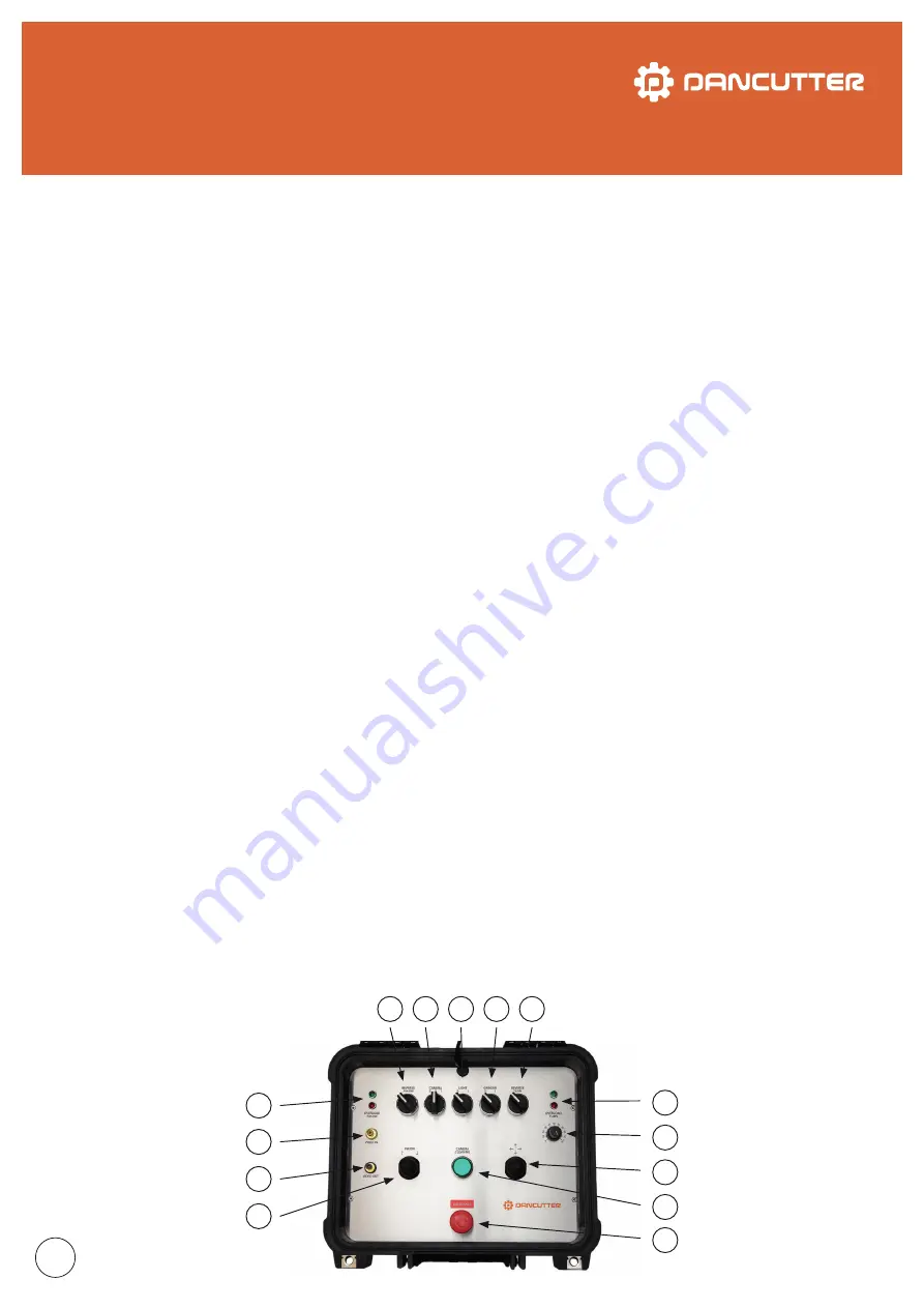
1. FW/BW:
use the joystick to operate the cutter’s forward/
back movement.
2. VIDEO OUT:
outlet for showing the camera image on an
external screen.
3. VIDEO IN:
outlet for an external camera, if necessary (turn
the camera knob to “2”).
4. OVERLOAD FW/BW: the green LED should preferably flicker/
shine when the forward/back drive is operating. If the electric
motor is overloaded, the red LED will shine and an acoustic
alarm will sound for about 5 seconds. After this, the power
supply to the motor will be disconnected. The controls will
switch back on again after about 10 seconds.
5. REVERSE FW/BW:
this function reverses the signal to the
“FW/BW” joystick. Use this function if you are using an exter-
nal camera sees in the opposite direction from the camera
on the cutter. Turn the knob to the “left” position for normal
operation. Turning the knob to the right makes the joystick
work in reverse.
6. CAMERA:
use this switch to turn on the camera on the cut-
ter. (Pos. “2”: external camera) (Pos. “1”: camera on the cutter)
7. LIGHT:
use this switch to turn on the camera light.
8. GRINDER:
start the Cutter by turning the switch to pos. “1”.
9. REVERSE TURN:
this function reverses the signal to the
joystick “turn/raise arm”. Use this function if you are using an
external camera which sees in the opposite direction from
the camera on the cutter. Turn the knob to the “left” position
for normal operation. Turning the knob to the right makes
the joystick work in reverse. The “arm: up/down” function is
unchanged regardless of the switch position.
10. OVERLOAD TURN: the green LED should preferably flicker/
shine while the rotation function is operating. If the electric
motor is overloaded, the red LED will shine and an acoustic
alarm will sound for about 5 seconds. After this, the power
supply to the motor will be disconnected. The controls will
switch back on again after about 10 seconds.
11. REGULATOR:
use this knob to adjust the speed of the
cutter’s rotation function. The function is not available on DC
MAXI FLEX.
12. TURN/RAISE ARM:
moving the joystick right or left acti-
vates the cutter’s rotation function to the right/left. Pulling the
joystick away from the screen raises the cutter arm. Pushing
the joystick towards the screen lowers the arm. The up/down
speed of the arm is preset at the factory.
13. CAMERA CLEAN:
pressing the button activates the
camera cleaner. The button shines green when the function is
active. Press the button again to switch off the camera cleaner
(the light in the button will turn off).
14. EMERGENCY:
activating the emergency-stop button will
disconnect all 24 V DC supplying the electric motor and the
magnetic valves for air. The only function retained is the power
supply for the cutter’s camera so it is possible for the operator
to view the cutter as it is being withdrawn from a pipeline.
WiFi is built into the control unit to provide a wireless connec-
tion for a VR headset (optional accessory).


