background image

Speaker cables 

Install the speaker cables first. We recommend the use of high-quality cables terminated with spade or 
ring lugs that will fit the amplifier’s binding posts. We advise against the use of bare-wire connections.

Note that the positive (+) binding post has a red ring and the negative (-) binding post has a black ring. 
Double-check to confirm that you are connecting your speaker cable’s conductors to the appropriate 
binding posts—red to positive, black to negative. If your cables are marked to show desired signal flow, 
orient the cable so that the installation conforms to the cable manufacturer’s instructions.

Carefully loosen each speaker binding post to install speaker cables tipped with spade lugs or rings. 
Turn counter-clockwise to loosen. If using spade lugs, insert each spade lug so that its two tines 
straddle the binding post, then tighten the binding post nut with a binding post wrench. If using rings, 
remove the binding post nut entirely, place the ring on the binding post, then replace the nut and 
tighten it securely.

A firm connection, tight enough that the spade lug or ring cannot move, is all that’s needed. Do not 
use a conventional wrench to tighten the binding posts. 

Be sure the wires are not in contact with 

one another.

Interconnect cables 

Connect the XLR cable to the input by pushing the cable onto the jack. To release the XLR cable, push 
on the small tab on the end of the jack then grasp the cable by the plug and gently pull it out. Never 
grasp interconnect cables by the cable itself—you could damage the cable.

12-volt trigger input and output 

The 1/8-inch (3.5mm) 12-volt trigger input and output jacks allow the Relentless to turn on automatically 
when connected to a preamp or home automation system with 12-volt trigger output. Connect a 
cable with a 1/8-inch plug (stereo or mono) on each end from the preamp’s 12-volt trigger output 
to the amplifier’s 12-volt trigger input, and a second cable of the same type from the amp’s 12-volt 
trigger output to the other amplifier’s 12-volt trigger input. The amplifiers will automatically power up 
whenever the preamp is powered up.

MAKING CONNECTIONS TO THE 

RELENTLESS MONOBLOCK AMPLIFIER

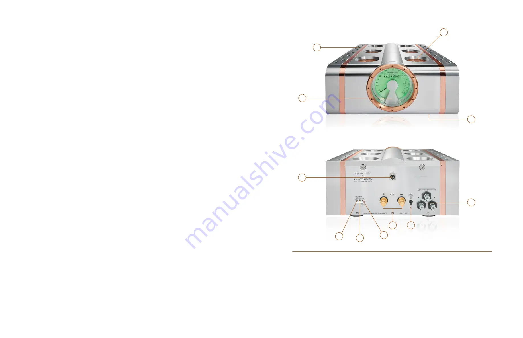
 1.  Heat sink venturis

 2.  Top panel vents

 3.  Power  meter

 4.  Standby/power  button

 5.  XLR audio input

 6.  12-volt on/off trigger input

 7.  12-volt trigger output

 8.  Three-position toggle switch for 
    power meter brightness

 9.  Speaker cable binding posts

 10.  Main power switch

 11.  AC power cord terminals

4

2

3

1

6

7

9

10

8

5

11

Содержание Relentless Mono Amplifier

Страница 1: ...OWNER S MANUAL RELENTLESS MONOBLOCK AMPLIFIER ...

Страница 2: ...With the Relentless every speaker ever made can achieve its best possible performance I designed every stage of the Relentless from scratch The unique input stage achieves extraordinarily low noise and distortion by assuring that the positive and negative halves of the signal are perfect opposites of each other even if the incoming signal is not perfectly balanced The gain stage operates in the cu...

Страница 3: ... protective vinyl sleeve 1 owner s manual 4 pair of white lifting gloves 1 microfiber cleaning cloth 1 AC power cord selected for your voltage and socket requirements 1 ratchet with custom carbon fiber socket for binding post Unpacking the Relentless monoblock amplifier from its case Each Relentless amplifier weighs 570 lbs 258 kg so it requires at least four strong adults to lift Be sure to have ...

Страница 4: ...se a conventional wrench to tighten the binding posts Be sure the wires are not in contact with one another Interconnect cables Connect the XLR cable to the input by pushing the cable onto the jack To release the XLR cable push on the small tab on the end of the jack then grasp the cable by the plug and gently pull it out Never grasp interconnect cables by the cable itself you could damage the cab...

Страница 5: ...correct power connections will void your warranty and can damage your amplifier To connect the power cable remove the two screws on the plastic cover that protects the AC cable terminal connections Remove the nut on the amp s positive terminal place the spade ring of the positive conductor of the cable over the terminal then replace the nut Tighten the nut firmly but gently with a 3 4 inch socket ...

Страница 6: ...EPC 117 Modular Output Board 1 08 18 with Cable Connector 2 56 EPC 121 Input Board 1 08 18 1 57 EPC 130 Power Relay 1 08 18 1 58 EPC 132 Speaker Relay Board 1 08 18 2 59 EPC 133 Voltage Select 1 08 18 1 60 C4 104080 7 Transformer Housing Sm 1 61 MTP 281 Transformer Housing Lg 1 62 meter glass 1 63 switch 1 64 power post 3 65 high speed rectifier mounting pad 4 66 capacitor 6 67 NC3FD V XLR Connect...

Страница 7: ... against manufacturing defects and defects in materials for five years from the date of purchase from an authorized Dan D Agostino Master Audio Systems dealer subject to the conditions listed below 1 The warranty covers only new products purchased from an authorized Dan D Agostino Master Audio Systems LLC dealer 2 The warranty is non transferable and is valid only for the original purchaser 3 The ...

Страница 8: ...put power 1 500 W RMS at 8Ω 3 000 W RMS at 4Ω 6 000 W RMS at 2Ω Output voltage 320 V peak to peak 113 V RMS Output current 400 A peak Slew rate 100 V μs Output impedance 0 03Ω 20 Hz to 20 kHz Damping factor 267 20 Hz to 20 kHz ref to 8Ω Power consumption Standby 40 W Idle 480 W Maximum 10 kW Input 1 balanced via XLR connector Outputs 1 pair binding posts Dimensions 22 5 x 11 5 x 32 5 in whd 57 2 x...

Страница 9: ...www dandagostino com 2018 DAN D AGOSTINO MASTER AUDIO SYSTEMS LLC ALL RIGHTS RESERVED Designed handmade and assembled in the USA using USA machinists vendors and parts procurement ...

Отзывы: