


Note:
(1) L is connected to VSS and H is connected to VDDIO
(2)
↑
stands for rising edge of signal
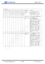
(3) SDI is shifted into an 8-bit shift register on every rising edge of SCL in the
order of D7, D6, ... D0. The level of D/C# should be kept over the whole byte.
The data byte in the shift register is written to the Graphic Display Data RAM
(RAM)/Data Byte register or command Byte register according to D/C# pin.
Figure 3.5-1: wire mode
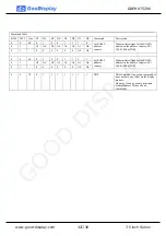
In the read operation, after CS# is pulled low, the first byte sent is command byte,
D/C# is pulled low. After command byte sent, the following byte(s) read are data
byte(s), so D/C# bit is then pulled high. An 8-bit data will be shifted out on every
clock falling edge. The serial data output SDO bit shifting sequence is D7, D6, to D0
bit. Figure 6-2 shows the read procedure in 4-wire SPI.
Figure 3.5-2: Read procedure in 4-wire SPI mode
GDEH075Z90
17
/
38
7.5 inch Series
www.good-display.com
GOOD DISPLAY
Содержание 07502-2
Страница 1: ...7 5 inch E paper Display Series GDEH075Z90 Dalian Good Display Co Ltd G O O D D I S P L A Y ...
Страница 9: ...1 6 Reference Circuit GDEH075Z90 9 38 7 5 inch Series www good display com G O O D D I S P L A Y ...
Страница 36: ...L long W wide D point size GDEH075Z90 36 38 7 5 inch Series www good display com G O O D D I S P L A Y ...
Страница 37: ...8 Packing GDEH075Z90 37 38 7 5 inch Series www good display com G O O D D I S P L A Y ...


