


VIP-5000 Series Quick Guide
DD2773153
Rev 06
30 January 2018
Page 2 of 6
201 Daktronics Drive
Brookings, SD 57006-5128
www.daktronics.com/support
800.325.8766
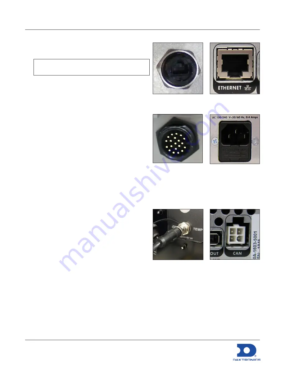
Connecting to the Network
1.
Connect one end of the RJ45 network cable to the
network port. Refer to
Figure 6
and
Figure 7
.
Note:
For a display-mount system, rotate the
connector
1
/
4
turn clockwise to lock.
2.
Connect the other end of the cable to the
computer or network.
Connecting Power
Display-Mount Systems (12VDC)
1.
Connect the breakout cable to the power/sensor
port. Refer to
Figure 8
.
2.
Rotate the connector
1
/
4
turn clockwise to lock.
3.
Connect the breakout cable to the power cord.
4.
Terminate the cord at the display’s power panel.
Rack-Mount Systems (120/240VAC)
1.
Connect the power cord to the power jack. Refer
to
Figure 9
.
2.
Plug the other end of the cord into an outlet.
Connecting Temperature/Light Sensors
Display-Mount Systems
1.
Connect the sensor cable’s M12 connector to the
temperature/light port. Refer to
Figure 10
.
2.
Turn the connector ring clockwise until tightened.
Rack-Mount Systems
Connect the sensor cable to the CAN port. Refer
to
Figure 11
.
Computer-to-Processor Setup
Connecting to the Processor
1.
Download the DisplayFind application from either the control software CD or the internet.
a.
Navigate to
dakfiles.daktronics.com
.
b.
Click
venus1500>Utils>DisplayFind>DisplayFind.exe
.
c.
Click
Run
to download the program or
Save
to save the file for later use.
Figure 6:
Display-Mount
Network Port
Figure 7:
Rack-Mount
Network Port
Figure 8:
Display-Mount
Power/Sensor Port
Figure 9:
Rack-Mount
Power Jack
Figure 10:
Display-Mount
Sensor Port
Figure 11:
Rack-Mount
Sensor Port


