


10
VIP 4500 Configuration Using Venus
®
7000 Software
6.
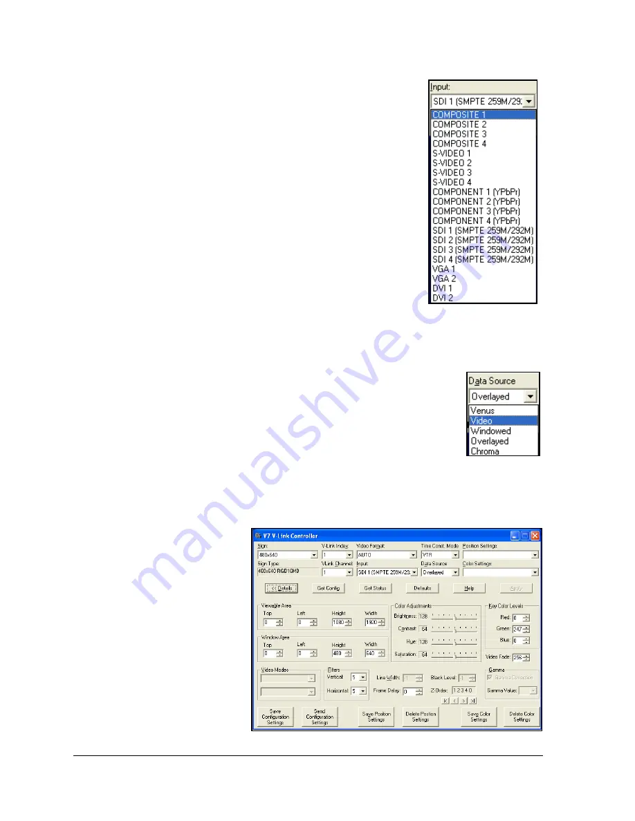
Click the
drop-down arrow
next to Input and select your
desired input. Users may also press
[Alt] + [I]
to move the
cursor to the Input text box and then use the
[up]
and
[down
arrows]
to select the desired input. After completing the setup
procedure and configuring the settings for this input, adjust
the settings for each of the other inputs as well.
7.
To make the Time Constant Mode adjustment, click the
drop-
down arrow
next to Time Const. Mode box and then select the
preferred mode.
Note:
VTR works well for most applications.
8.
Leave the Data Source setting on
Video
to play video content
on the display.
9.
Leave the Position Settings and Color Settings alone;
adjustments are made in
Steps 10-14
.
Default setting is
overlay.
10.
Click
Details
or press
[Alt] + [D]
. The V7 VLink Controller
The Viewable Area box determines what portion of the video feed displays.
The default setting is the largest area of acceptable video feed available for
display. This feed is centered and may be adjusted as desired. Change the
Top
and
Left
quantities to move the display area to the desired video
image area.
If adjusting the Viewable Area and/or Source Window settings, save those
settings. Click
Save Position Settings
or press
[Alt] + [
V
].
A Save Position
Settings dialog box opens. Type the name of the position settings (for
example, “Position 1”). Click
OK
or press
[Enter]
. This saves the settings
under the name entered.
Recall settings using
Position Settings.
Figure 7: Input Selector
Figure 8: Data
Source Selector
Figure 9: V7 V-Link Controller Dialog Box with Details